Communication bus suitable for use in a hazardous area of a process plant

a technology for communication buses and hazardous areas, applied in the direction of emergency protective arrangements for limiting excess voltage/current, overvoltage protection resistors, etc., can solve the problems of reducing the possibility of sparks or arcs that could ignite flammable atmospheres, difficult installation and maintenance, safety devices, etc., to eliminate or reduce the need for expensive energy-limiting barriers, reliable and inexpensive mechanisms

Active Publication Date: 2005-03-31
FISHER-ROSEMOUNT SYST INC
View PDF27 Cites 47 Cited by
  • Summary
  • Abstract
  • Description
  • Claims
  • Application Information

AI Technical Summary

Benefits of technology

[0009] The safety device provides a reliable and inexpensive mechanism for safely interrupting the flow of electrical signals along a communication bus located in a hazardous area upon the detection of a fault condition associated with the communication bus. The safety device eliminates or reduces the need for expensive energy-limiting barriers on the communication bus, which are often difficult to install and maintain. In addition, by bidirectionally interrupting the flow of electrical signals along each of the first and second transmission paths upon the detection of a fault condition associated with the communication bus, the safety device reduces the possibility of the occurrence of a spark or arc that could ignite a flammable atmosphere in a hazardous area.

Problems solved by technology

The safety device eliminates or reduces the need for expensive energy-limiting barriers on the communication bus, which are often difficult to install and maintain.
In addition, by bidirectionally interrupting the flow of electrical signals along each of the first and second transmission paths upon the detection of a fault condition associated with the communication bus, the safety device reduces the possibility of the occurrence of a spark or arc that could ignite a flammable atmosphere in a hazardous area.

Method used


Image

  • Communication bus suitable for use in a hazardous area of a process plant
  • Communication bus suitable for use in a hazardous area of a process plant
  • Communication bus suitable for use in a hazardous area of a process plant

Examples


Embodiment Construction

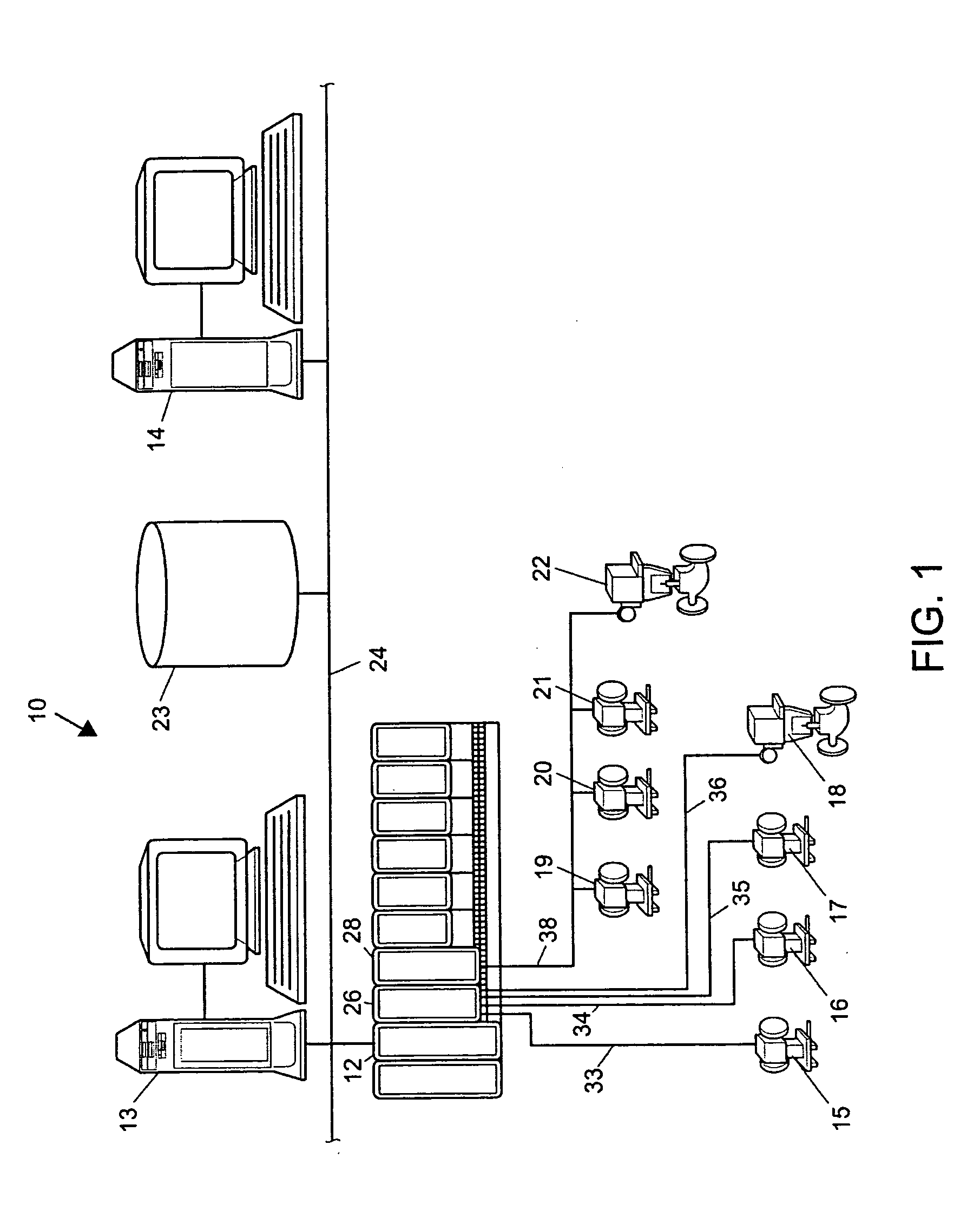
[0014] Referring now to FIG. 1, a process plant 10 includes a plurality of field devices 15-22 connected to a process controller 12 via one or more input / output (I / O) devices 26, 28. The process controller 12 may be a distributed control system (DCS) type controller such as, for example, a DeltaV™ controller sold by Emerson Process Management, or any other type of controller for use in controlling field devices 15-22 in any conventional or any other desired manner. The process controller 12 is capable of implementing a process control routine stored therein and / or capable of communicating with control elements such as function blocks located within, for example, smart field devices 19-22 distributed throughout the process plant 10.

[0015] The process controller 12 is communicatively coupled to one or more operator workstations 13, 14 via a communication bus 24. The communication bus 24 may use any desired or suitable local area network (LAN) or wide area network (WAN) protocol to pr...


PUM


Abstract

A communication bus suitable for use in a hazardous area of a process plant includes a first transmission path adapted to communicate electrical signals in a first direction, and a second transmission path adapted to communicate electrical signals in a second direction. A safety device is coupled to each of the first and second transmission paths and includes a control unit adapted to detect a fault condition associated with the communication bus. The safety device further includes a switch unit adapted to interrupt the flow of electrical signals along each of the first and second transmission paths in response to the detected fault condition. In this manner, the detection circuitry of the communication bus automatically reduces or prevents the occurrence of sparks or arcing in the event of a fault condition associated with the communication bus.

Description

TECHNICAL FIELD [0001] The present disclosure relates generally to a process plant and, more particularly, to a communication bus suitable for use in a hazardous area of a process plant. DESCRIPTION OF THE RELATED ART [0002] In process plants where flammable or combustible materials are present, potentially dangerous conditions exist due to the possibility that the flammable atmosphere may ignite. These conditions may occur in many industrial environments such as, for example, environments involving petroleum and other chemicals, flammable gases, combustible dusts, explosive vapors, etc. Standardized classifications for the various types of hazardous locations have been adopted and assigned by regulatory agencies and organizations according to the nature and type of hazard that is generally present or that may occasionally be present. To protect both plant personnel and property, precautions should be taken inside these hazardous areas to avoid the risk of electrical sparks or exces...

Claims


Application Information

Patent Timeline
Patent Type & Authority Applications(United States)
IPC IPC(8): H02H9/00H04L12/28H04L69/14H04L69/40
CPCH02H9/008H02H7/267H04L69/40
Inventor BURR, KENT A.LAW, GARY K.ANEWEER, TOM
Owner FISHER-ROSEMOUNT SYST INC
Why Eureka
Try Eureka