Capacitive proximity switch

a proximity switch and capacitive technology, applied in the direction of anti-theft devices, electrical locking circuits, electric devices, etc., can solve the problems of minor disruption in ease of operation, increase in current consumption of identification receivers, etc., and achieve the effect of less demands

Active Publication Date: 2005-03-31
IMF ELECTRONIC GMBH +1
View PDF10 Cites 188 Cited by
  • Summary
  • Abstract
  • Description
  • Claims
  • Application Information

AI Technical Summary

Benefits of technology

[0042] According to the last advantageous embodiment of the circuit arrangement, there is a second sensor, especially a second capacitive proximity switch, which acts as a rain sensor and preferably, moreover, also delivers the switching signal for locking the door lock, while the first capacitive proximity switch delivers only the switching signal for unlo

Problems solved by technology

For the described activation, this means that the second operating threshold is activated when rain is recognized by the capacitive proximity switch or by the evaluation unit, so that any small change in capacitance which has been measured by the capacitive proximity switch and which is caused by raindrops no longer leads to activatio

Method used


Image

  • Capacitive proximity switch
  • Capacitive proximity switch
  • Capacitive proximity switch

Examples


Embodiment Construction

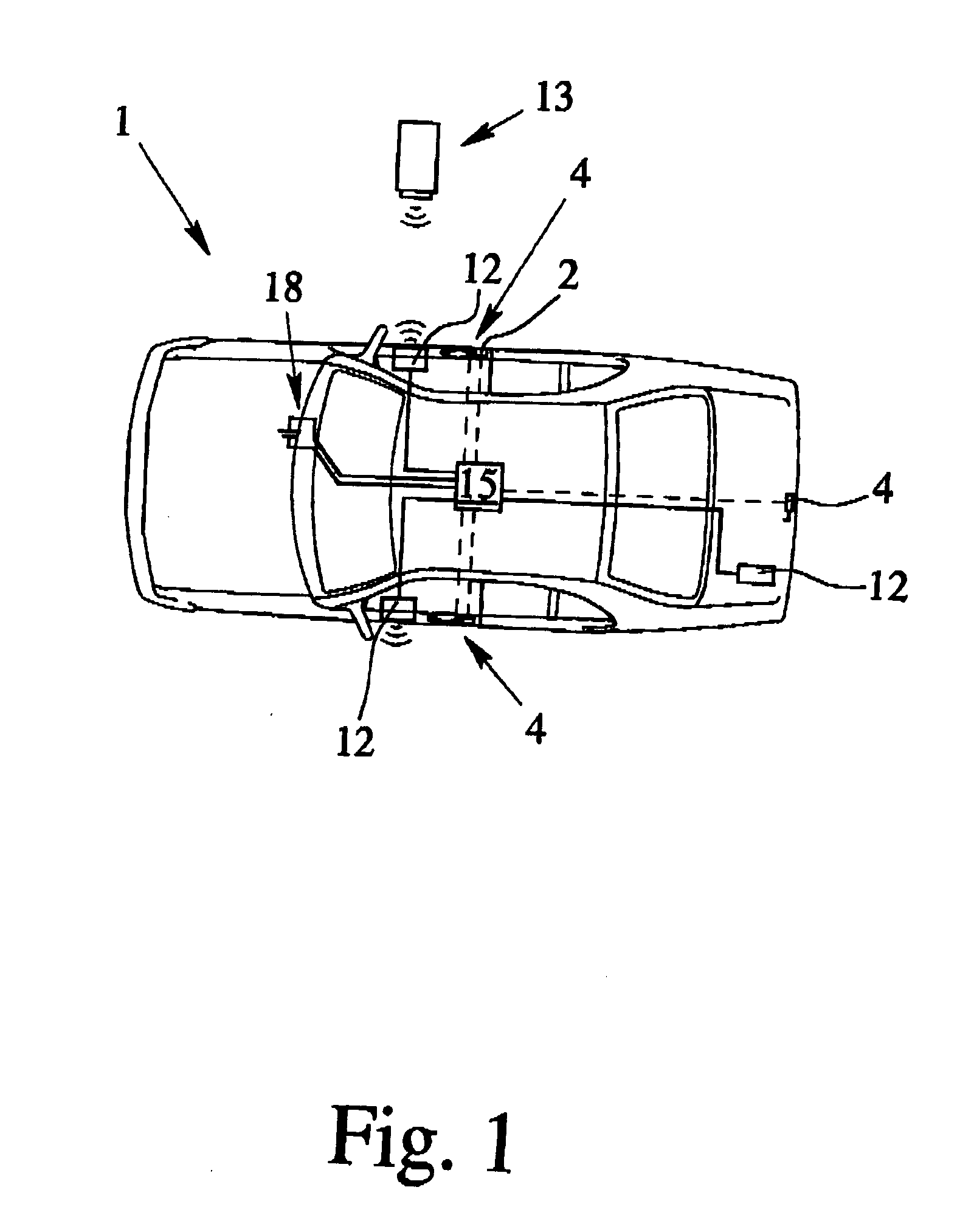
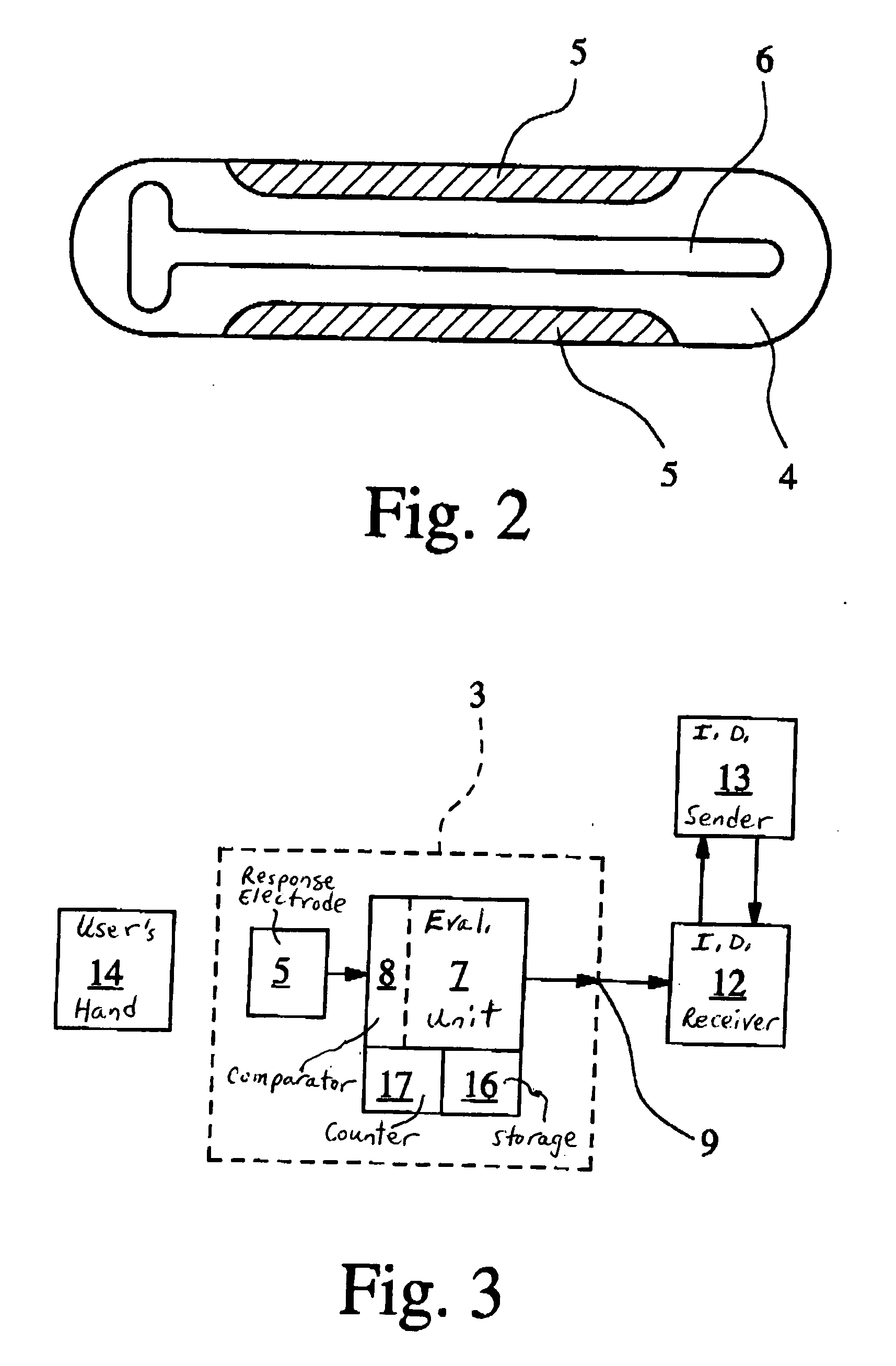
[0054]FIGS. 1 & 2, together, schematically show a motor vehicle 1 which has a circuit arrangement for locking and unlocking at least one door lock 2 with an electronic activation circuit and with a capacitive proximity switch 3, a response electrode 5 and a compensation electrode 6 of the proximity switch 3 being integrated in the door handle 4. The compensation electrode 6 is shown only in FIG. 2, and not in the simplified circuit diagram of the proximity switch 3 in FIG. 3. How a possible circuit diagram of a proximity switch 3 which, in addition to the response electrode 5, also has a compensation electrode 6 can look can be taken from FIG. 3 of U.S. Pat. No. 5,880,538.

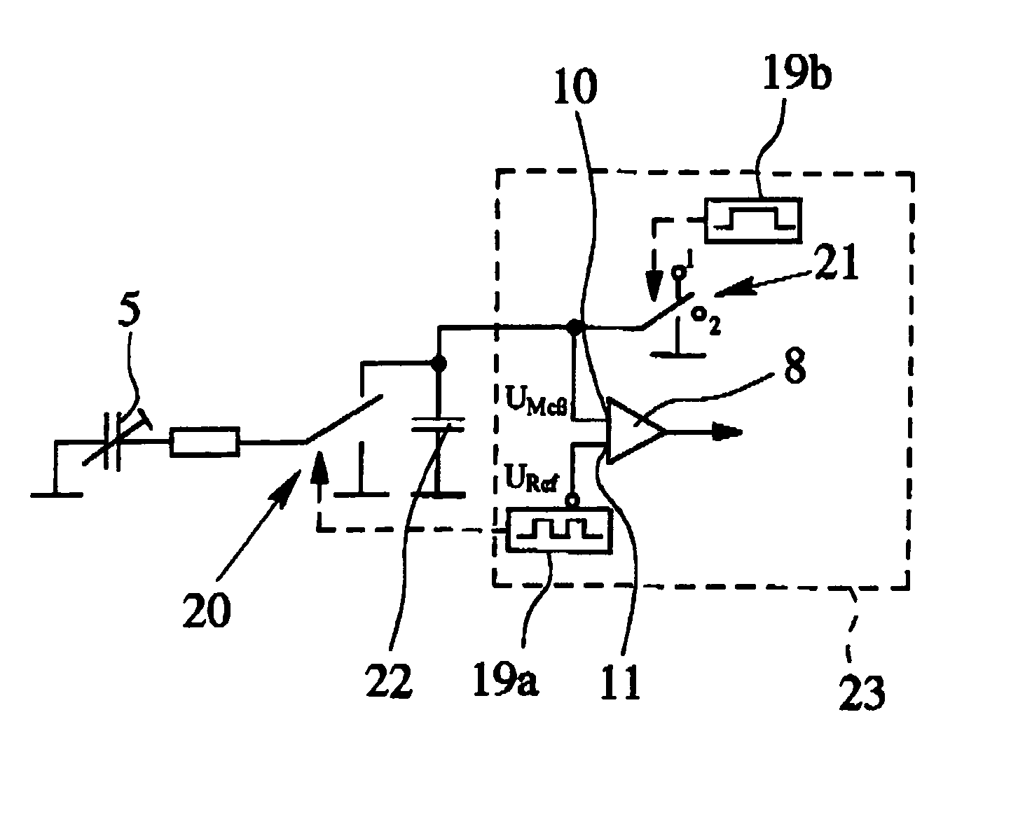
[0055] As follows from the block diagram of the circuit arrangement shown in FIG. 3, the capacitive proximity switch 3 includes, besides the electrode system which has the response electrode 5, an evaluation unit 7 with a comparator 8 which has an operating threshold S1, and a switching output 9. At the input 10 o...


PUM


Abstract

A capacitive proximity switch for detecting the change in the capacitance relative to a setpoint capacitance by the approach or retreat of an object in the sensitive area of a proximity switch, especially for use in the door handle of a motor vehicle, provides reliable error detection and error suppression at a fundamentally high sensitivity of the capacitive proximity switch by utilizing an evaluation unit that evaluates a measured value of the change in capacitance over time and depending on the time behavior of the measured value activates changes the operating threshold from a first threshold (which can be caused by a false object coming into or out of the sensitive area of the proximity switch) to a higher second threshold which can be reached only at a relatively greater change in capacitance caused by a target object coming into or out of the sensitive area of the proximity switch.

Description

BACKGROUND OF THE INVENTION [0001] 1. Field of the Invention [0002] The invention relates to a capacitive proximity switch for detecting the change in the capacitance relative to a setpoint capacitance Cset by the approach or retreat of an object in the sensitive area of a proximity switch, especially for use in the door handle of a motor vehicle, with an electrode system which has at least one response electrode and with a switching output, the measured value which corresponds to the change in capacitance being compared to an operating threshold S1 and at the switching output a switching signal being produced depending on the measured value. [0003] 2. Description of Related Art [0004] As is recognized, capacitive proximity switches respond when the capacitance between the response electrode and a reference electrode reaches or exceeds a certain value, specifically because the response electrode approaches an object which for its part is galvanically or capacitively connected to the...

Claims


Application Information

Patent Timeline
IPC IPC(8): E05B49/00E05B65/12E05B65/20H03K17/955
CPCE05B81/77H03K2217/960715H03K17/955E05B81/78E05B81/76E05B49/00
Inventor SCHULZ, JOERGHEILIG, GERHARDRICHTER, HEIDRUNSTEEGMANN, BERNDWITTE, MARTINUSELLI, GIANNI
Owner IMF ELECTRONIC GMBH
Why Eureka
Try Eureka