Display apparatus having heat transfer sheet

a technology of heat transfer sheet and display apparatus, which is applied in the direction of identification means, semiconductor/solid-state device details, instruments, etc., can solve the problems of heat negatively affecting the organic illumination layer, panel and control, and reducing the precision of the display, so as to reduce the overall noise generation of the display apparatus

Inactive Publication Date: 2005-03-31
SAMSUNG SDI CO LTD
View PDF16 Cites 53 Cited by
  • Summary
  • Abstract
  • Description
  • Claims
  • Application Information

AI Technical Summary

Benefits of technology

[0022] Yet another exemplary embodiment of the present invention discloses a display apparatus in which a heat transfer sheet includes a plurality of pores and is attached to a display panel such that discharge noise generated by the display panel is dissipated in the pores to reduce overall noise generation of the display apparatus.
[0023] In still yet another exemplary embodiment of the present invention, there is provided a display apparatus in which electromagnetic waves generated during discharge are absorbed in a display panel and grounded through a chassis base to prevent transmission of the EM waves to a circuit.

Problems solved by technology

Such heat may affect the panel and controls, thereby reducing the precision of the display.
The heat negatively affects the organic illumination layer because organic material is more susceptible to heat damage than inorganic material.
Heat is also generated in the panel of the FED and if the heat is not efficiently discharged from the FED, the panel is negatively affected.
However, in conventional devices there are typically large areas where gaps of air exist in the contact surfaces between these elements reducing adhesion, reducing the heat discharge efficiency.
However, this configuration has a disadvantage as it is difficult to obtain a reliable degree of adhesivity with large screen sizes.
The plasma display device realizes a uniform distribution of heat through this type of configuration, however, this type of structure also has disadvantages as it creates a large profile and generates noise.
Bright image stickings may result when there are differences in the image pattern being displayed as heat is concentrated at specific regions of the display.
This bright image sticking is caused by temperature changes affecting phosphor illumination.
However, it is difficult to prevent the formation of an air layer because graphite is hard and easily cracks.
This air layer reduces the actual area of attachment to the plasma panel, thereby minimizing heat discharge efficiency.
Also, the graphite thermal spread sheet is limited in its ability to alleviate external vibrations and shocks.

Method used


Image

  • Display apparatus having heat transfer sheet
  • Display apparatus having heat transfer sheet
  • Display apparatus having heat transfer sheet

Examples


Embodiment Construction

[0052] Reference will now be made in detail to embodiments of the present invention, examples of which may be illustrated in the accompanying drawings.

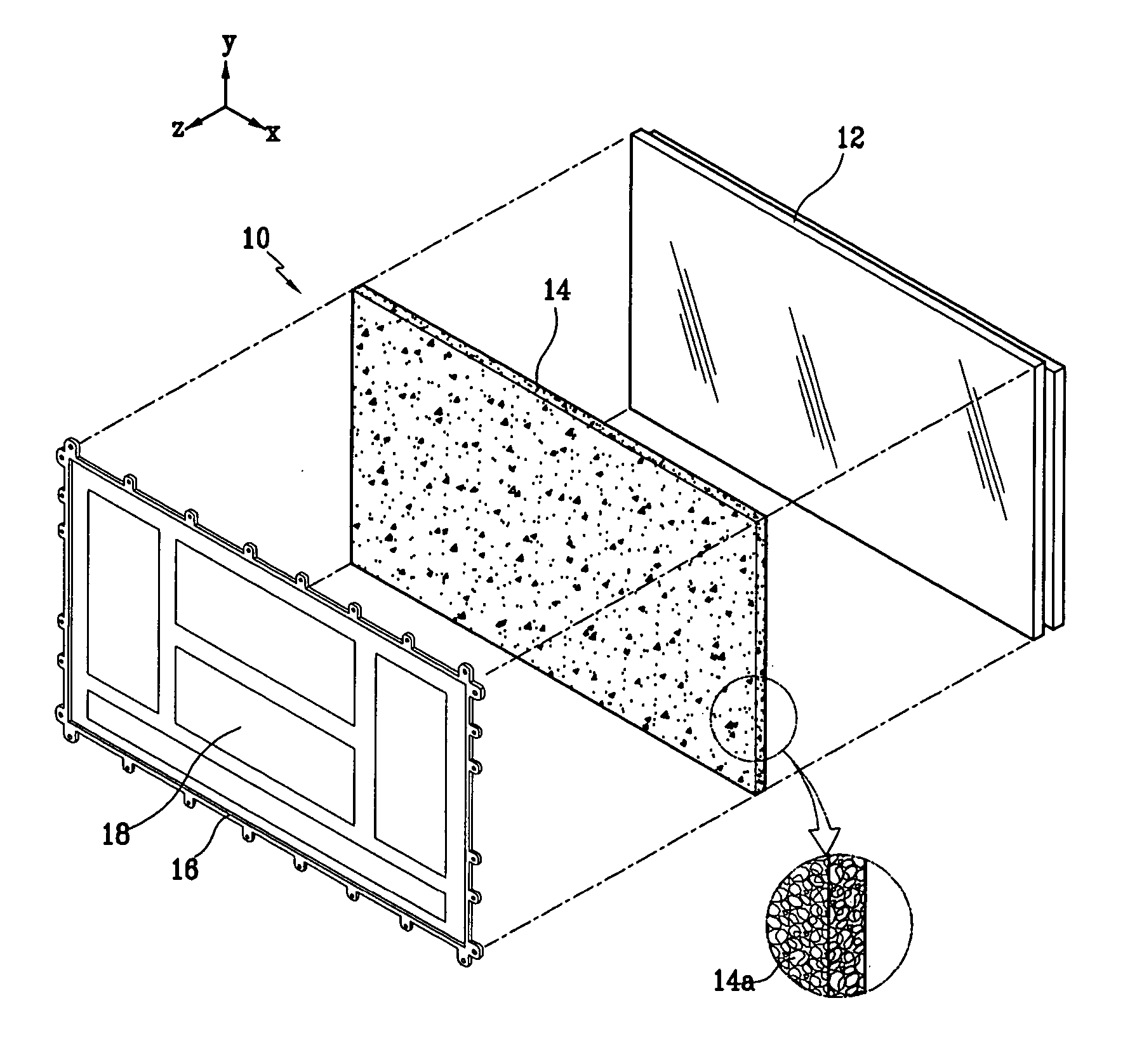
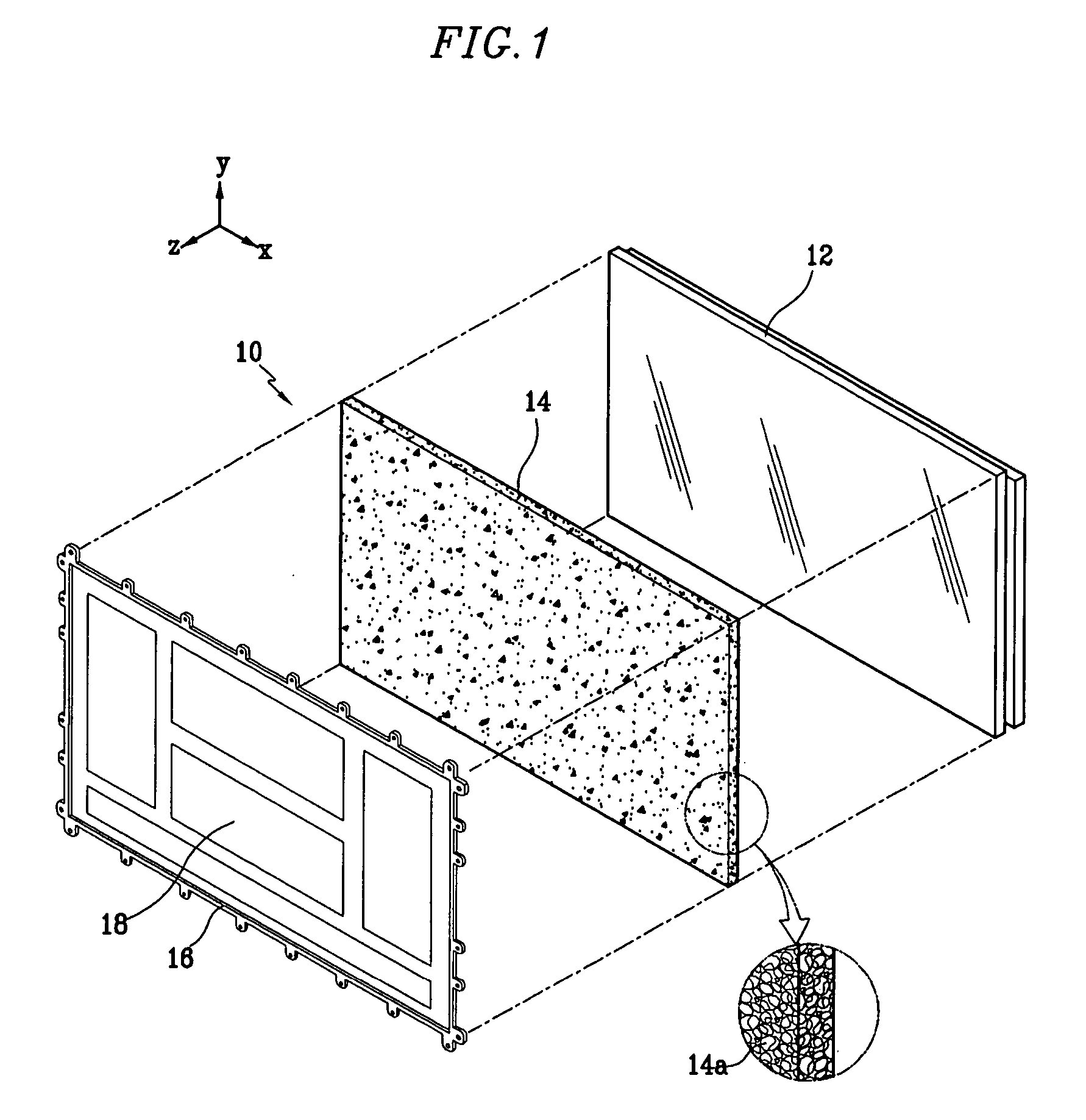
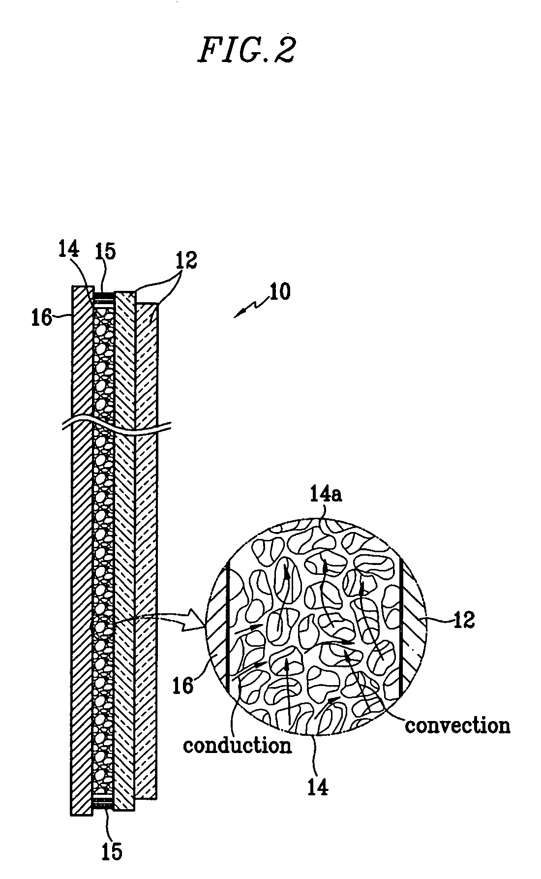
[0053]FIG. 1 shows a partial exploded perspective view of a plasma display device according to an exemplary embodiment of the present invention. FIG. 2 shows a partial side sectional view and a partial exploded view of a plasma display device in an assembled state according to an exemplary embodiment of the present invention.

[0054] Referring to FIGS. 1 and 2, a plasma display device 10 includes a display panel 12 and a chassis base 16. The display panel 12 and the chassis base 16 each have a predetermined thickness and may have a substantially rectangular configuration. The chassis base 16 and display panel 12 each have two opposing surfaces encompassed by sides. The display panel 12 may be mounted to the chassis base 16 with one of its faces being substantially adjacent to a face of the chassis base 16. Circuit elements 19 for driv...


PUM

PropertyMeasurementUnit
porosityaaaaaaaaaa
load ratioaaaaaaaaaa
porosityaaaaaaaaaa

Abstract

A display apparatus includes a display panel and a heat transfer sheet mounted adjacent to one surface of the display panel. A plurality of pores are formed in the heat transfer sheet. The heat transfer sheet may have an open cell-type structure and/or a closed cell-type structure. The open cell-type structure includes pores that are interconnected. The closed cell-type structure includes pores formed that are not in communication with each other, rather these pores may be independently formed.

Description

BACKGROUND OF THE INVENTION [0001] 1. Field of the Invention [0002] The present invention relates to a display apparatus, and more particularly, to a display apparatus including an assembly for efficiently discharging heat generated by a display panel. [0003] 2. Discussion of the Related Art [0004] As societies become more information-based, the demand for better displays increases. In response to this demand, display devices are becoming increasingly varied in configuration and operation. These display devices may vary, for example, from the displays used in digital wristwatches and calculators, to small and large size television screens and displays having high resolutions. These display devices have different sizes, display capacities, display colors, and other different characteristics, which may depend on their intended use. [0005] There has been a particularly marked increase in the demand for display devices having a thin profile (e.g., flat panel displays) for use in laptop ...

Claims


Application Information

Patent Timeline
Patent Type & Authority Applications(United States)
IPC IPC(8): G02F1/133G02F1/1333G09F9/00H01J7/24H01J17/16H01J17/28H01J31/12H01L23/373H01L51/52H04N5/64H04N5/66H05K7/20
CPCG02F1/133385H01L23/3733H01L51/5237H01L51/529H01L2924/12044H01L2924/0002H05K7/2099H01L2924/00H10K50/841H10K50/84H10K50/87H01J17/28H01J11/10G02F1/13H10K50/00
Inventor KIM, KI-JUNGKANG, TAE-KYOUNGCHO, IN-SOO
Owner SAMSUNG SDI CO LTD
Why Eureka
Try Eureka