Light emitting diode glow tube

a diode glow tube and light-emitting diode technology, applied in the field of low-light output accent lighting, can solve the problems of low efficiency, unsuitable for use as accent lights, light failure, etc., and achieve the effects of adequate accent illumination, enhanced light guide efficiency, and high light transmission efficiency

Inactive Publication Date: 2005-03-31
ROSSTECH SIGNALS
View PDF5 Cites 3 Cited by
  • Summary
  • Abstract
  • Description
  • Claims
  • Application Information

AI Technical Summary

Benefits of technology

[0006] In particular the present invention includes a glow tube accent light which has an end-lit acrylic light guide acting as both a light diffuser and emitter. Since the light guide of the present invention possesses high light transmission efficiency, the glow tube may require only a single LED which is optically coupled to one end of the light guide to provide adequate accent illumination. To enhance the efficiency of the light guide, the end opposite the LED may be made optically reflective with a white coating. Thus, the opposite end reflects emitted light from the LED back into the light guide.
[0007] Further efficiency enhancements may be included in the glow tubes of the present invention. For instance, the ends of the light guide may be smoothed to a mirror finish by clean flame polishing. Additionally, the light guide may be adhered to the light guide track housing. The adhesive creates a light seal which results in the light from the LED impinging on the track side of the light guide to be reflected to the front of the light guide. Thus, the light seal significantly increases the light output of the glow tube. Moreover, to enhance the consistency of the light output along the length of the light guide, longitudinal etches may be added to the light guide to more evenly distribute the light emission along the light guide. Accordingly, the LED illuminates the glow tube to a level and consistency suitable for viewing in low ambient light environments.
[0008] In a first embodiment, the accent light includes an LED and a light guide with proximal and distal ends. The LED is optically coupled to the proximal end and the distal end reflects the LED light back into the guide. Additionally, the distal end may include a reflective coating and the guide may be acrylic. Moreover, the guide may be supported by a vinyl housing adhered to the light guide whereby the light output of the glow tube in the viewing direction is increased significantly relative to an isolated light guide. Also, a longitudinal etch on the acrylic guide may make the light output reasonably consistent along the guide. Thus, the present invention provides accent lights which diffuse and output a high percentage of the source light emitted by the LED.
[0009] In another embodiment, a method of enhancing the light output from an accent light is provided. The method includes optically coupling a light emitting diode to a proximal end of a light guide and reflecting light from a distal end of the guide back into the guide. Additionally, the method may include coating the distal end with a white reflective material. Moreover, the light guide may be an acrylic tube. A support channel may also be provided for the acrylic tube and the two adhered together. Adding a support channel and adhering the channel to the acrylic tube significantly increases the light output of the accent light. Furthermore, a longitudinal etch may be made on the acrylic tube to make the diffuse light output along the length of the acrylic tube of a relatively uniform consistency. Thus, the present invention provides a method of enhancing the light output of an accent light to utilize a high percentage of the light emitted by the LED.

Problems solved by technology

Incandescent lights generally suffer from a number of disadvantages, which make them unsuitable for use as accent lights.
First, they tend to be unreliable and prone to damage resulting in light failure, particularly from vibration, shock and corrosion.
Moreover, an incandescent light consumes a relatively large amount of power, most of which is lost as sensible heat, not emitted as visible light, resulting in low efficiencies.
Additionally, incandescent lights can cast a harsh light from a concentrated point source which further makes them unsuitable for use as accent lights in low ambient light conditions.
But neon accent lights also suffer from disadvantages similar to those of incandescent lights.
Neon lights are fragile and require excessive power in comparison to solid state LED lighting.
Neon lights are also generally too bright for use as accent lights, particularly in low ambient light conditions.

Method used


Image

  • Light emitting diode glow tube
  • Light emitting diode glow tube
  • Light emitting diode glow tube

Examples


Embodiment Construction

[0016] The following description of the embodiment(s) is merely exemplary in nature and is in no way intended to limit the invention, its application, or uses.

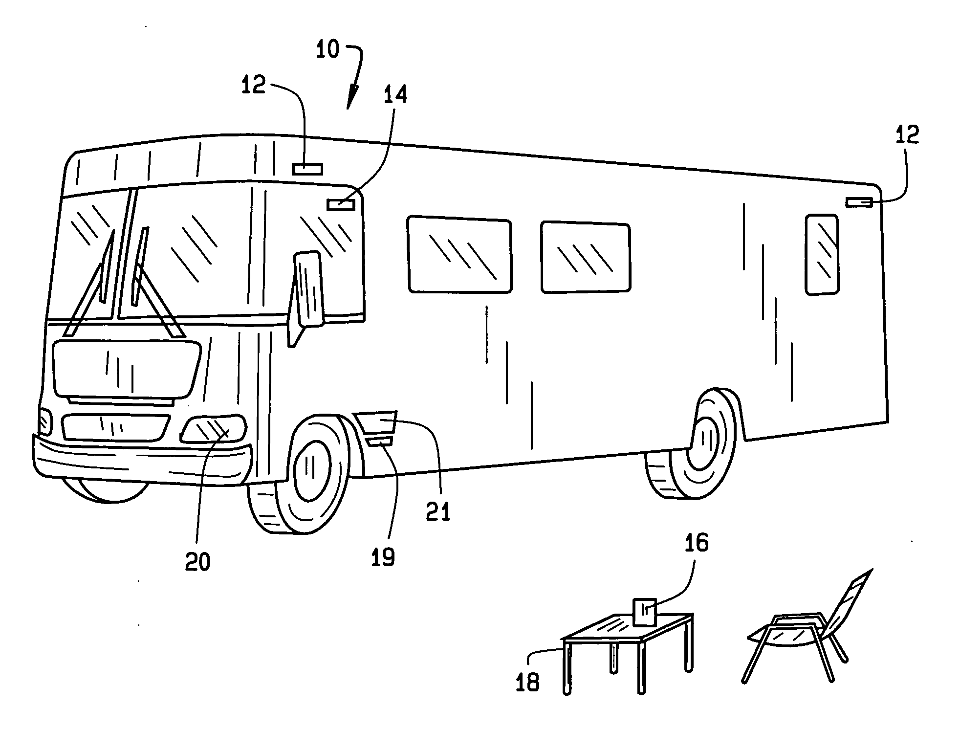
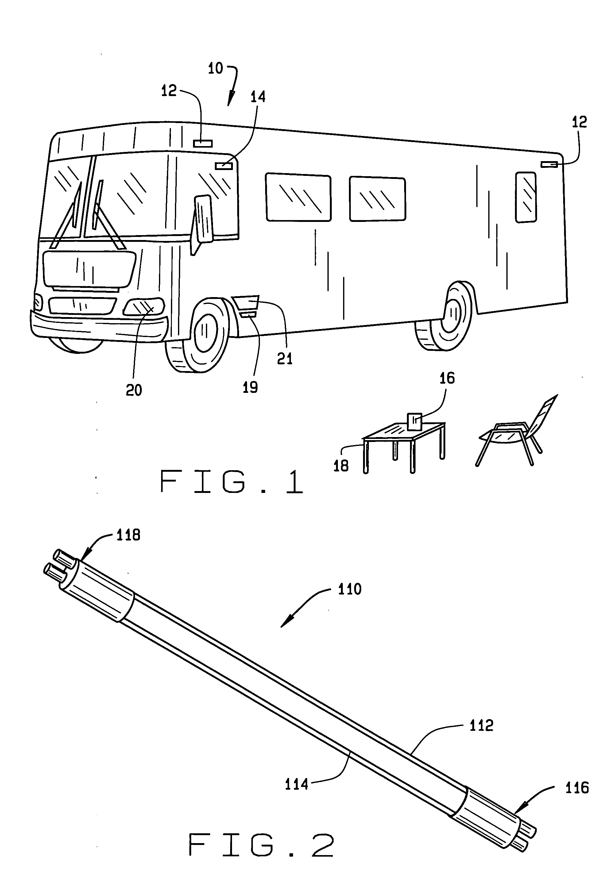
[0017] As seen in FIG. 1, consumers frequently decorate their consumer products by adding accent lights to the product and its environs. In the exemplary scene shown in FIG. 1, a recreational vehicle 10 represents a typical consumer good which may be decorated with accent lights. Accent lights 12 are shown along the top edge of the recreational vehicle 10. As well, accent lights 14 may be included within the cabin of the recreational vehicle 10. A battery powered accent light 16 may also be set on (or affixed to) structures 18 near the recreational vehicle 10. Additionally, a low intensity location marking light 19 may be provided on the edge of a step 21 leading into the recreational vehicle 10. Being exposed to the weather, the accent lights 12 and 16 and the marking light 19 are waterproof and weatherproof, though the acce...


PUM


Abstract

A method of accent lighting and an accent light including an LED and a light guide with polished proximal and distal ends. The LED is optically coupled to the proximal end and the distal end reflects the LED light back into the guide. Additionally, the distal end may include a reflective coating and the guide may be acrylic. Moreover, the guide may be supported by a vinyl support glued to the guide whereby the light output about doubles. Also, a longitudinal etch on the acrylic guide may make the light output about consistent along the guide.

Description

FIELD OF THE INVENTION [0001] The present invention relates to accent lighting, and more particularly to low light output accent lighting BACKGROUND OF THE INVENTION [0002] Many consumers prefer to decorate their belongings with accent lights. Recently, for example, accent lights for automobiles, RV's and other vehicles have become popular. For another example, consumers frequently purchase hot tubs, saunas, and other leisure goods decorated with accent lights. Additionally, after market accent lights may be purchased by the consumer to decorate belongings which they already own, such as decks, patios, dock systems and so on. Likewise, low intensity lights (similar to accent lights) are preferred for location finding (e.g. in darkened theaters, outdoor areas at night, or pathways) and other general marking applications. [0003] Incandescent lights generally suffer from a number of disadvantages, which make them unsuitable for use as accent lights. First, they tend to be unreliable an...

Claims


Application Information

Patent Timeline
Patent Type & Authority Applications(United States)
IPC IPC(8): B60Q1/32B60R13/00B60R13/10F21V8/00
CPCB60Q1/32G02B6/001B60R13/105B60R13/00
Inventor LOVE, DAVID A.
Owner ROSSTECH SIGNALS
Why Eureka
Try Eureka