
Free space optical (FSO) device providing power reduction features and related methods

a free space optical and feature technology, applied in the field of communication systems, can solve the problems of rf transmission systems, difficult to achieve, and optical transceivers that have to be precisely aligned with one another to operate properly, and achieve enhanced distortion mitigation features and convenient transportation

Inactive Publication Date: 2005-03-31
HARRIS CORP
View PDF11 Cites 7 Cited by
  • Summary
  • Abstract
  • Description
  • Claims
  • Application Information

AI Technical Summary

Benefits of technology

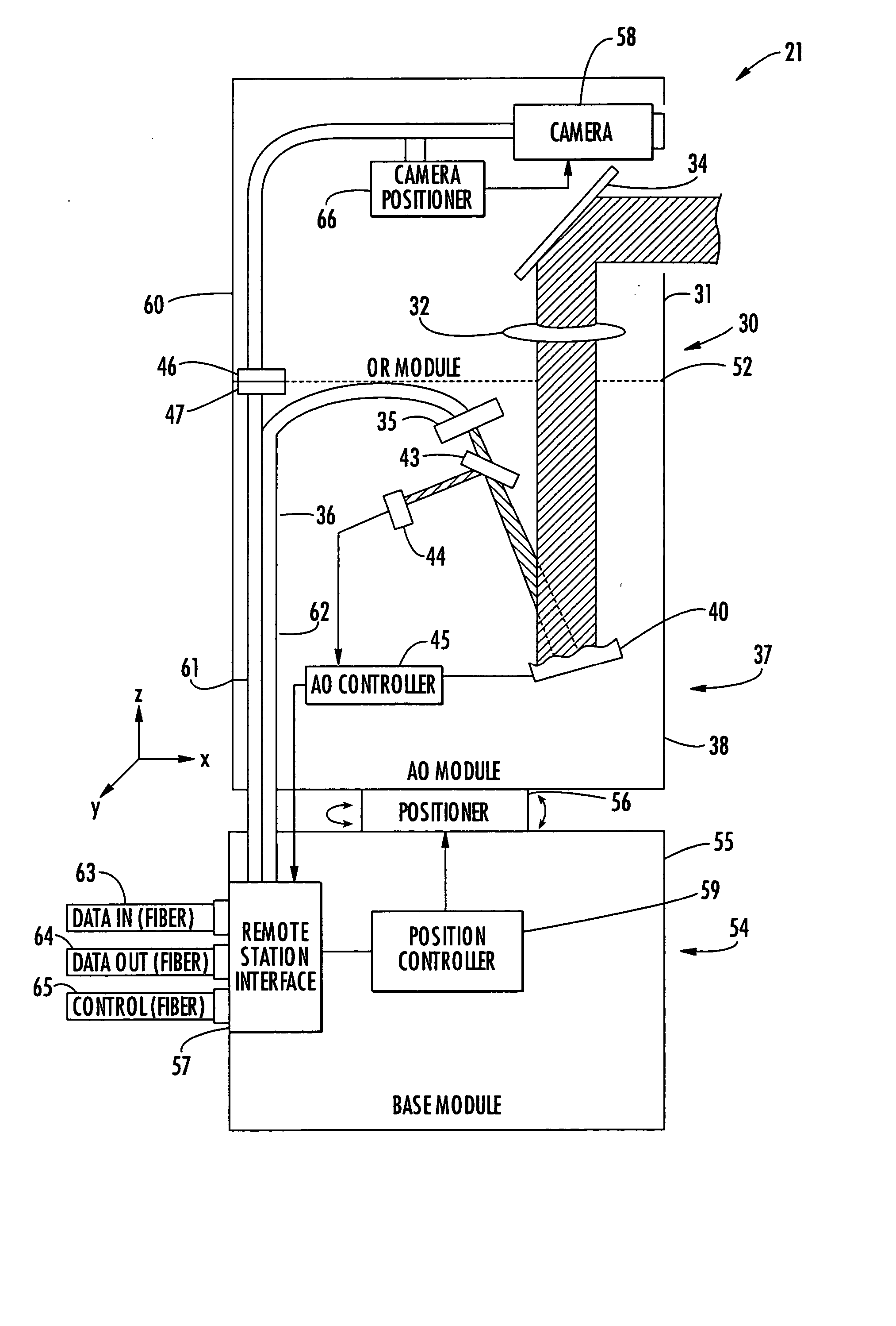
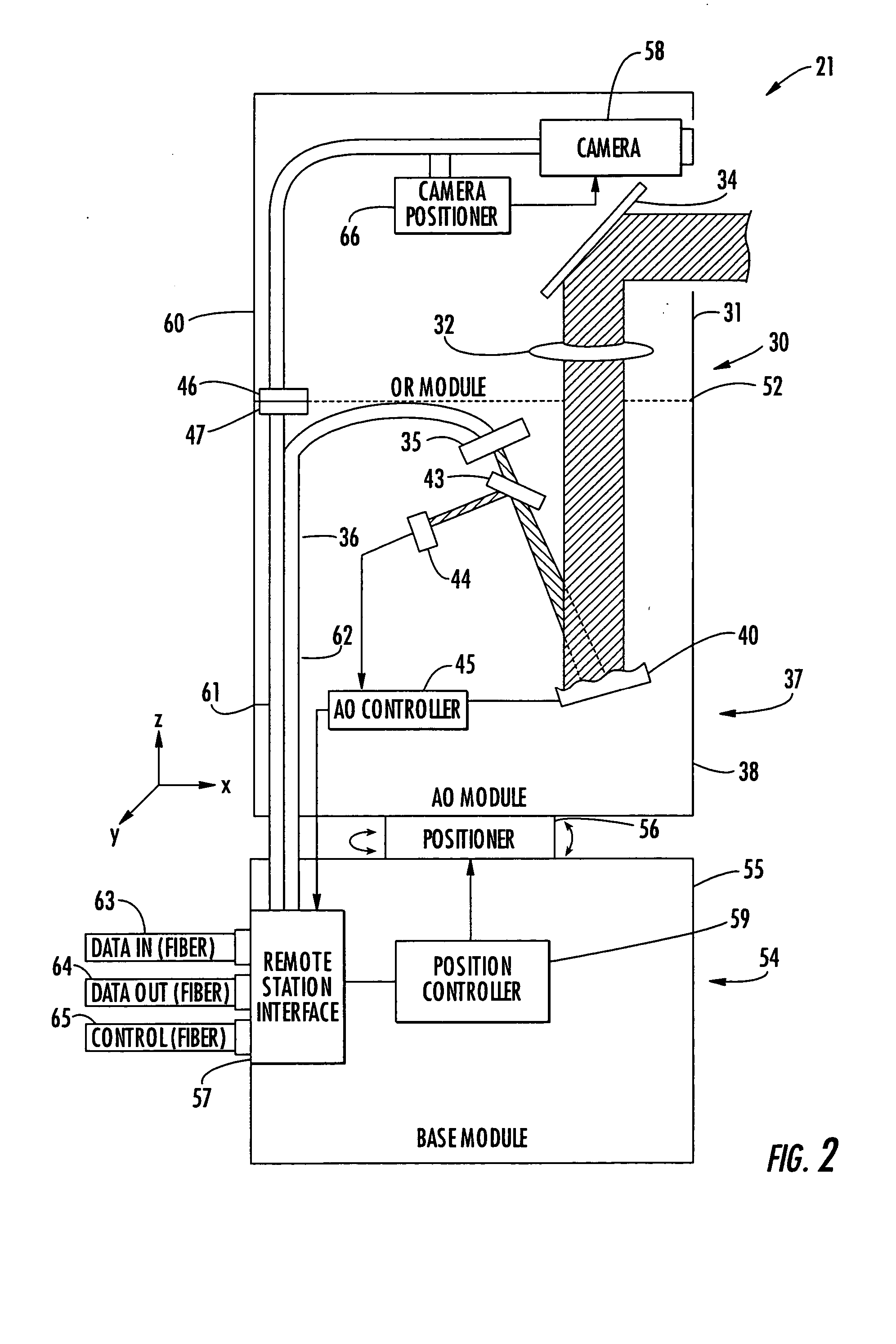
[0011] The deformable mirror may further include a reflective deformable member mounted on the array of actuators. Additionally, the AO module may further include a thermal stress isolation mount connecting the deformable mirror to the AO housing. Accordingly, stresses experienced by use of the FSO communications module in harsh environmental conditions may be substantially isolated from the deformable mirror to enhance reliability and longevity thereof.
[0013] Accordingly, the modular FSO communications device may advantageously be relatively small compared to prior art devices. That is, rather than using a relatively large telescopic zoom lens with a large aspect ratio to cover an extended range, different interchangeable OR modules may be used for different applications based upon the requisite focal length for a given application. Accordingly, this leads to a reduction in overall size and cost. Moreover, because the OR modules are interchangeable, a customer may use the same AO module for numerous applications, rather than having to purchase a new AO module for each application.

Problems solved by technology

Moreover, optical signals can generally be more focused than RF signals, and are thus more difficult to intercept and less likely to cause interference with other transmissions.
Despite the advantages of FSO systems, one drawback they have with respect to RF transmission systems is that the optical transceivers have to be precisely aligned with one another to operate properly.
This may be difficult to do when the optical transceivers are spaced a significant distance from one another, such as a few miles or more.
As such, they cannot be easily re-directed to communicate with other transceivers as can a directional RF antenna, for example.
Another potential drawback of FSO systems is that the optical wavefronts being transmitted from the transceivers are subject to atmospheric distortion, such as from heat rising from the earth, etc.
While adaptive optics do provide enhanced reliability, they are typically fairly expensive to implement.
Moreover, a relatively large power supply on the order of several hundred volts may be required for such devices.
As such, with the requisite power and control circuitry required for the deformable mirror, an FSO system incorporating such technology can be fairly large and cumbersome to move and set up.
Yet, this may also increase the cost of the transceiver assembly, in addition to increasing its overall size.

Method used


Image

  • Free space optical (FSO) device providing power reduction features and related methods
  • Free space optical (FSO) device providing power reduction features and related methods
  • Free space optical (FSO) device providing power reduction features and related methods

Examples


Embodiment Construction

[0022] The present invention will now be described more fully hereinafter with reference to the accompanying drawings, in which preferred embodiments of the invention are shown. This invention may, however, be embodied in many different forms and should not be construed as limited to the embodiments set forth herein. Rather, these embodiments are provided so that this disclosure will be thorough and complete, and will fully convey the scope of the invention to those skilled in the art. Like numbers refer to like elements throughout.

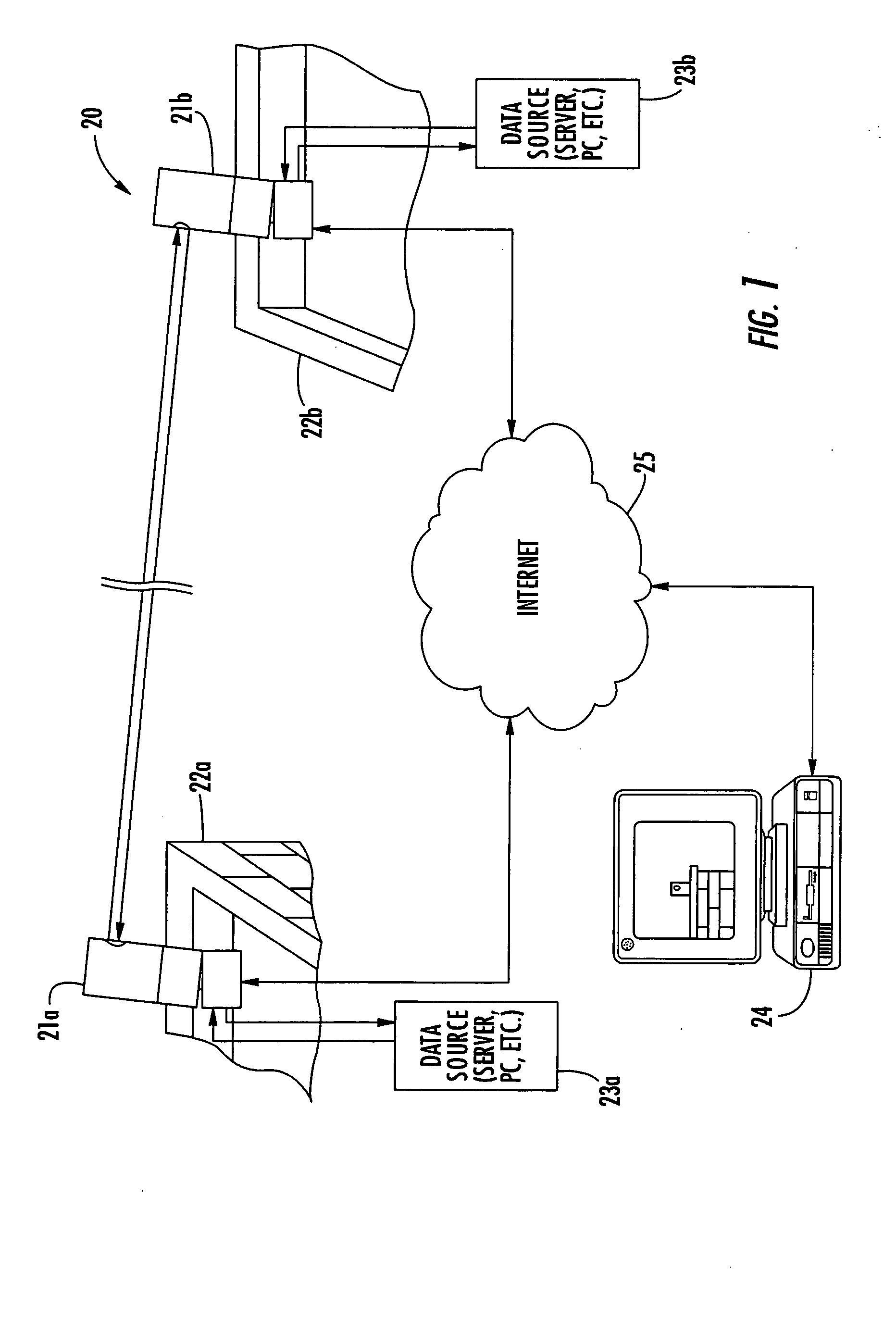
[0023] Referring initially to FIGS. 1 through 3, a free space optical (FSO) communications system 20 includes first and second modular FSO communications devices 21a, 21b aligned for optical communication therebetween. In the illustrated example, the FSO communications devices 21a, 21b are positioned on rooftops of buildings 22a, 22b, and each is connected to a respective data source 23a, 23b (e.g., a server or personal computer). That is, the modular FS...


PUM


Abstract

A free space optical (FSO) communications device may include a plurality of power supplies having different respective output voltages. The FSO communications device may further include an adaptive optics (AO) module including an AO housing and a deformable mirror carried thereby. The deformable mirror may include an array of actuators each operating based upon a supplied voltage. In addition, a power controller may also be included for selectively driving the array of actuators using a desired one of the power supplies to conserve electrical power.

Description

FIELD OF THE INVENTION [0001] The present invention relates to the field of communications systems, and, more particularly, to free space optical (FSO) communications systems and related methods. BACKGROUND OF THE INVENTION [0002] Interest in free space optical (FSO) communications continues to grow as the demands for higher bandwidth and faster data rates continue to increase. Generally speaking, an FSO system includes a pair of optical transceivers spaced apart from one another that transmit information back and forth using optical (e.g., laser) transmissions. Optical transmissions provide a wider bandwidth than other wireless communications mediums, such as RF frequency signals. Moreover, optical signals can generally be more focused than RF signals, and are thus more difficult to intercept and less likely to cause interference with other transmissions. [0003] Despite the advantages of FSO systems, one drawback they have with respect to RF transmission systems is that the optical...

Claims


Application Information

Patent Timeline
Patent Type & Authority Applications(United States)
IPC IPC(8): H04B10/10
CPCH04B10/1125
Inventor TEGGE, EDWARD HARRIS JR.BALL, DONALD M.
Owner HARRIS CORP
Learn More