Sleeve on a drum and changing said sleeve

a technology of sleeve and drum, which is applied in the direction of electrographic process, corona discharge, instruments, etc., can solve the problems of not all kinds of sleeves being securely attached to the drum, the process of replacing the sleeve from the drum with compressed air fails, etc., and achieves great precision

Active Publication Date: 2005-03-31
THE PROCTER & GAMBLE COMPANY +1
View PDF22 Cites 15 Cited by
  • Summary
  • Abstract
  • Description
  • Claims
  • Application Information

AI Technical Summary

Benefits of technology

[0010] The drum is used in a particularly beneficial manner, as an imaging cylinder in an electro-photographic printing machine. Using the drum as an imaging cylinder also fulfills the increased demand for imaging cylinders with respect to precision fitting of the sleeve on the drum, where great precision is required for transfer of the image. In addition, because such drums are often replaced, the drum is capable of serving as a coated drum in a printing machine, for example, as a fuser roller, a pressure roller, or an intermediate roller.

Problems solved by technology

A disadvantage of this prior art solution is the fact that a compressed air apparatus, along with a compressor for providing compressed air at several bars, must be available.
With the prior art process, not all kinds of sleeves can be securely attached to a drum.
At a certain thickness and with certain characteristics of the material, the process for replacing the sleeve from the drum by compressed air fails to work.
For example, sleeves made of thick metal cannot be slid onto a drum.
The result is that metal sleeves with a smaller wall thickness are manufactured in order to assure that they can be mounted on a drum, whereby the manufacturing process becomes more complicated and expensive.

Method used


Image

  • Sleeve on a drum and changing said sleeve
  • Sleeve on a drum and changing said sleeve
  • Sleeve on a drum and changing said sleeve

Examples


Embodiment Construction

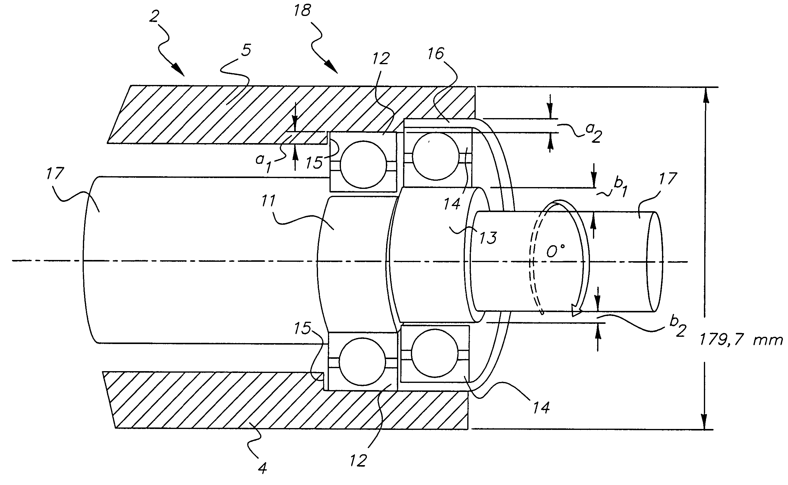
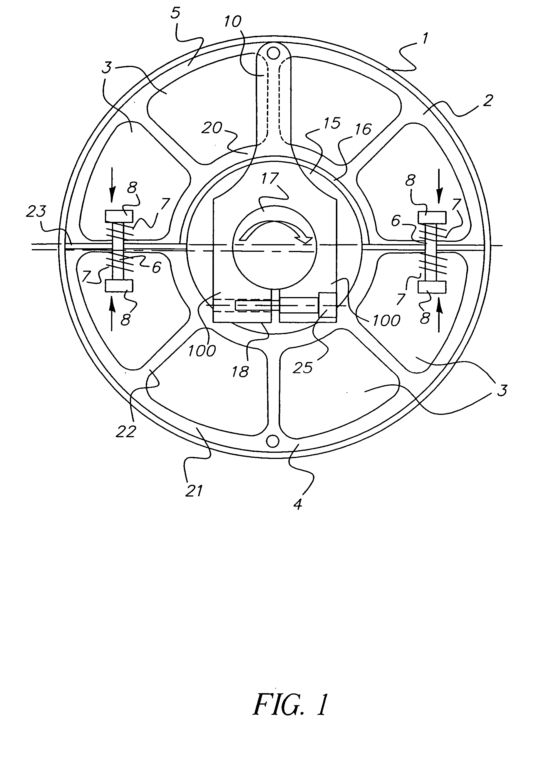
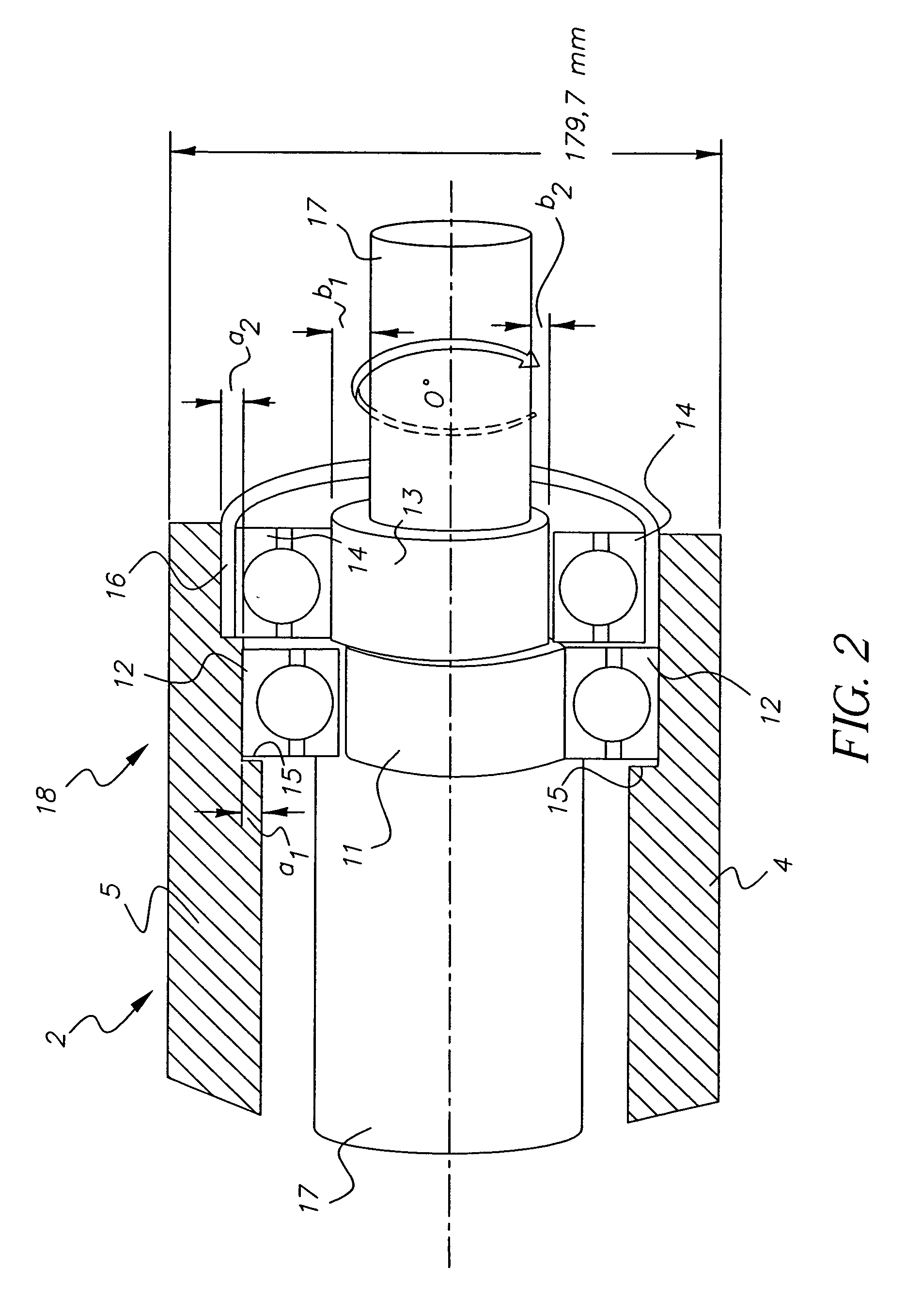
[0028] Referring now to the accompanying drawings, FIG. 1 shows schematically, a side view of an exemplary drum 2, for example, for use as an imaging cylinder in an electro-photographic printing machine. The drum 2 can also be used, for example, to hold a sleeve that is being processed, i.e., the drum 2 is in such case an apparatus used for manufacturing and processing sleeves 1, and serves as a temporary mount. The drum 2 incorporates an eccentric mechanism 18 that is described below and is shown in FIG. 1 as an extruded profile. Other constructions of the drum 2 are feasible. The drum 2 has an inner bearing seat 20 and an outer bearing seat 21 that has a larger diameter than the inner bearing seat 20. The inner bearing seat 20 and the outer bearing seat 21 are joined together by ribs 22 that extend from the inner bearing seat 20 to the outer bearing seat 21, connect the two bearing seats, and are preferably manufactured as a unit from the same material as the bearing seats. Betwee...


PUM

PropertyMeasurementUnit
depth a1aaaaaaaaaa
diameteraaaaaaaaaa
timeaaaaaaaaaa

Abstract

In replacing a sleeve on a printing machine drum, the diameter of the drum is reduced by moving the drum parts toward one another to facilitate removing the sleeve, and/or mounting another sleeve onto the drum, and increasing the drum diameter by moving the drum parts away from one another.

Description

FIELD OF THE INVENTION [0001] The invention pertains to a sleeve on a drum and a process for changing a sleeve on a drum. BACKGROUND OF THE INVENTION [0002] In the printing industry a number of rollers and drums are used for various purposes. Drums in printing machines are often equipped with sleeves that have various layers, and depending upon the use of the drum, fulfill different functions. For example, imaging cylinders in a photoelectric printing machine are equipped with photoelectric sleeves, that are capable of accepting a latent electrostatic image to which toner particles adhere, whereby a printed image is created that is transferred to a printing medium when the imaging cylinder is rolled over the printing medium. The sleeves on the drums are replaced from time to time, whereby the drum as the element that supports the sleeve, continues to be used, and is not replaced. [0003] Prior art provides, for example, a compressed air mechanism for replacing the sleeve, which makes...

Claims


Application Information

Patent Timeline
Patent Type & Authority Applications(United States)
IPC IPC(8): B41F27/10F16C13/00
CPCB41F27/105B41P2227/21Y10T29/49558G03G2215/00962F16C13/00
Inventor NAGY, ANDREAS GUSTAVCOMPERA, CHRISTIANDRAEGER, UDORAMM, TORSTENGREINER, ADOLFMATHES, EDWIN
Owner THE PROCTER & GAMBLE COMPANY
Why Eureka
Try Eureka