Handover for use with adaptive antennas

a technology of adaptive antennas and handovers, applied in the field of mobile radio communication, can solve the problem that the radio network cannot tell the mobile which secondary pilot channel to use, and achieve the effects of less interference spread, less transmit power, and more efficient radio transmission

Inactive Publication Date: 2005-03-31
TELEFON AB LM ERICSSON (PUBL)
View PDF11 Cites 83 Cited by
  • Summary
  • Abstract
  • Description
  • Claims
  • Application Information

AI Technical Summary

Benefits of technology

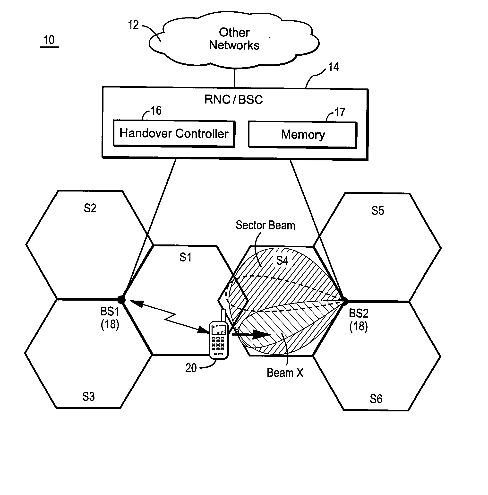
[0014] Several advantages flow from the present invention. First, because the handover radio link is established specifically for a narrow antenna beam, the radio transmission is more efficient. Second, there is less interference spread in the system and less transmit power required to communicate with the mobile station. Third, less interference and transmit power ultimately results in increased overall system performance. Fourth, radio resource management algorithms may be based upon resources allocated per antenna beam rather than resources allocated for the entire sector cell. As a result, the RNC can better control the resources in the system. For example, one part of the cell (one or a few beams) maybe overloaded while other parts are virtually unloade

Problems solved by technology

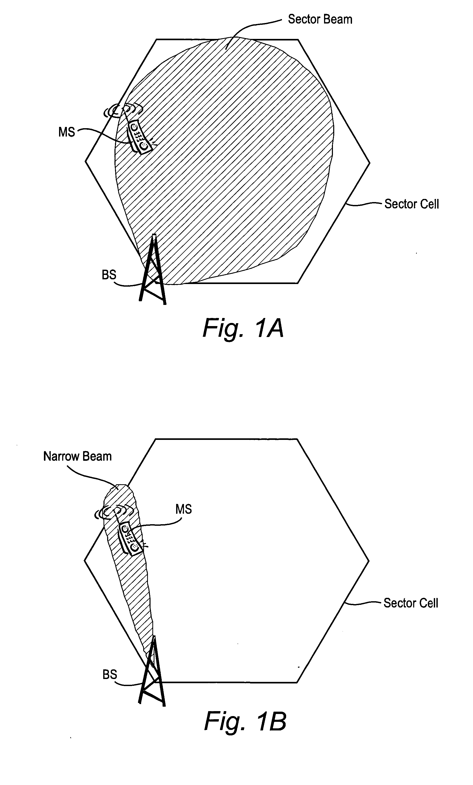
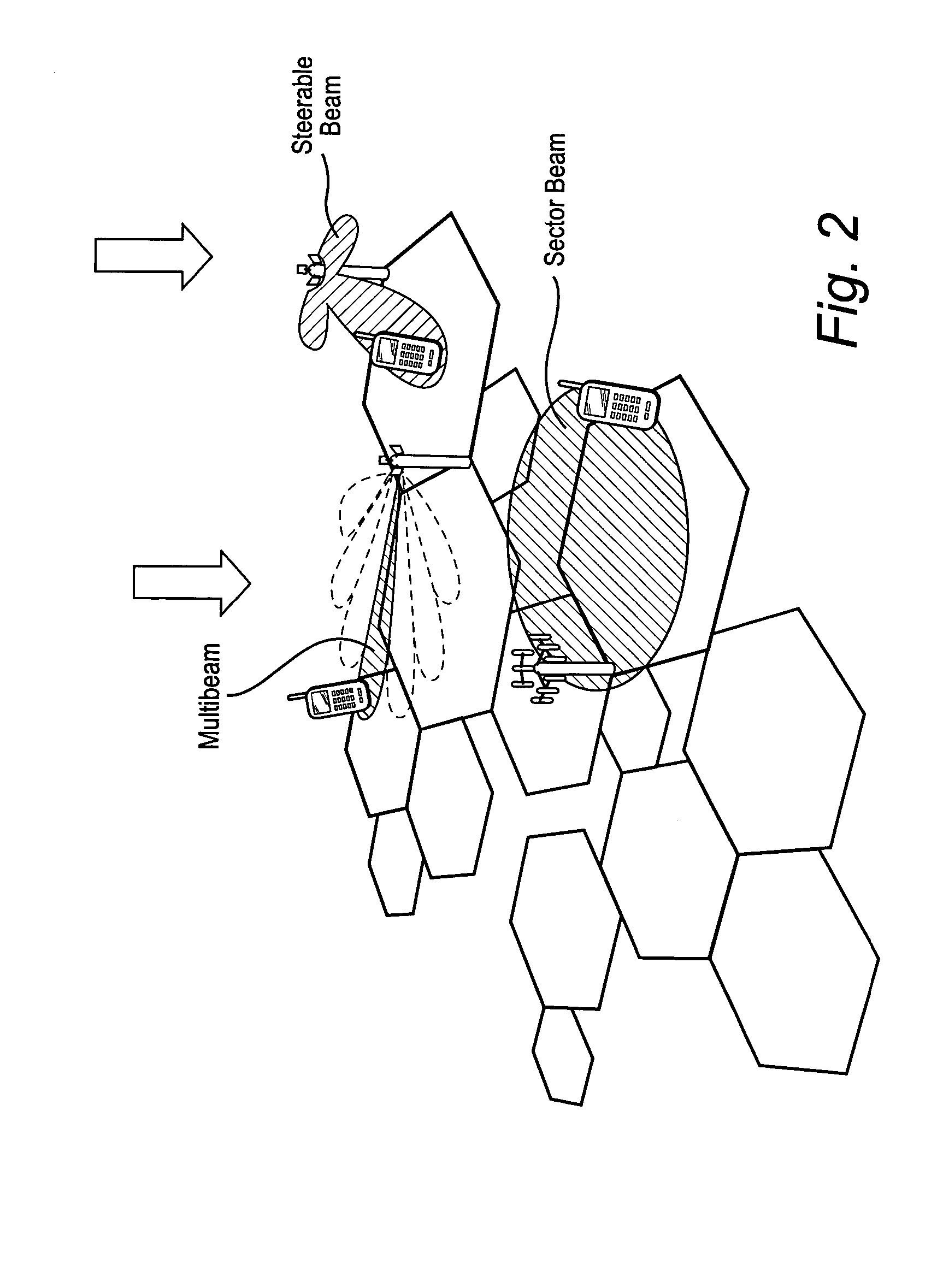
A problem arises in handover situations where a neighboring sector cell to which a handover connection is to be or may be established employs one or more adaptive antennas.
Such radio channel differences between wide and narrow antenna b

Method used


Image

  • Handover for use with adaptive antennas
  • Handover for use with adaptive antennas
  • Handover for use with adaptive antennas

Examples


Embodiment Construction

[0025] For purposes of explanation and not limitation, the following description sets forth specific details, such as particular electronic circuitry, procedures, techniques, etc., in order to provide an understanding of the present invention. But it will be apparent to one skilled in the art that the present invention may be practiced in other embodiments that depart from these specific details. In other instances, detailed descriptions of well-known methods, devices, and techniques, etc., are omitted so as not to obscure the description with unnecessary detail. Individual function blocks are shown in one or more figures. Those skilled in the art will appreciate that functions may be implemented using discrete components or multi-function hardware. The processing functions in particular may be implemented using a programmed microprocessor or general-purpose computer, using an application specific integrated circuit (ASIC), and / or using one or more digital signal processors (DSPs). ...


PUM


Abstract

Handover procedures take into account adaptive antennas that employ narrow, directional antenna beams. A connection is established with a mobile station by way of an originating radio base station. Downlink signal quality measurements associated with cell-wide transmissions from neighboring base stations are detected by the mobile station and reported to the radio network. The handover target base station is determined based upon those signal quality measurements. A desired antenna beam at the target base station is also determined for communicating with the mobile station based on uplink measurements made by the target base station. A handover connection is established between the target base station and the mobile station using the desired antenna beam at the target base station.

Description

BACKGROUND OF THE INVENTION [0001] The present invention relates to mobile radio communications, and in particular, to mobile radio communications systems that support diversity handover. [0002] In a code division multiple access (CDMA) mobile communications system, spreading codes are used to distinguish information associated with different mobile stations or base stations transmitting over the same radio frequency band. In other words, individual radio “channels” correspond to and are discriminated on the basis of these spreading codes. Spread spectrum (e.g., CDMA) communications permit mobile transmissions to be received at two or more (diverse) base stations and be processed simultaneously to generate one received signal as well as signals from multiple base stations to generate one received signal in the mobile. [0003] Because of these combined signal processing capabilities, it is possible to perform a handover of a mobile call from one base station to another base station, o...

Claims


Application Information

Patent Timeline
IPC IPC(8): H04W36/08H04W36/30
CPCH04W36/30H04W16/28
Inventor GORANSSON, BO
Owner TELEFON AB LM ERICSSON (PUBL)
Why Eureka
Try Eureka