Pultruded fibrous composite strip with width and thickness tapered ends for wind turbine spar caps

a composite strip and wind turbine technology, applied in the field of wind turbine spar caps, can solve the problems of large tapering regions, less durable consumables used in the machining process, and inability to meet the requirements of machining,

Active Publication Date: 2022-03-22
SIEMENS GAMESA RENEWABLE ENERGY AS
View PDF9 Cites 0 Cited by
  • Summary
  • Abstract
  • Description
  • Claims
  • Application Information

AI Technical Summary

Benefits of technology

[0010]An aspect relates to a pultruded fibrous composite strip for wind turbine spar caps that at least partially obviates the aforementioned three main problems of durability of consumables used in the machining process, potential environmental contamination, and wastage of material during machining. Furthermore, it is also desired that the pultruded fibrous composite strip reduced stress concentration in specific spanwise positions of the blade.
[0014]In another embodiment of the strip, the first and the second polygonal faces are parallel to each other. Thus, tapering in width of the edge region starts later as compared to the tapering in thickness with reference to the intermediate region from which the edge region emanates. Thus, providing a design flexibility which may be adapted according to the desired use of the strip for example position of the strip in the stack of strips forming the spar cap of the blade.
[0017]The aforementioned strip of the present technique has several advantages. First, since tapering of the longitudinal end or termination or edge region is both in width and thickness, the edge of the tapering is not a straight line of length same as width of the strip as was in conventional strip 201a of FIG. 5, but a slanted line whose length is greater than the width of the strip in the intermediate region, and thus stress at termination, and particularly at the edge of these terminations or edge regions is distributed along a greater area in the present strip as compared to the conventional strip 201a of FIG. 5, thus at least partially obviating the stress concentration happening in the conventional strip 201a of FIG. 5. Furthermore, since the tapering is also in width one side of the tapered end terminates before the other side of the same tapered end, for example one side tapers at 1:100 to 1:20 whereas the other side tapers at 1:100 to 1:20 and this terminates before the former side and thus volume of the tapered region is less spread as compared to the conventionally known tapered region as shown in FIG. 5 in which both side taper at same rate within the conventionally known range of 1:100 to 1:50. Thus, lesser machining is required, which saves time and positively impacts durability of consumables used in the machining process. Furthermore, since lesser area has been machines the loss of peel-ply is lesser which in turn decreases potential environmental contamination.

Problems solved by technology

One of the major downsides of using CFRP in form of conventional strip 201 arises from their longitudinal ends or abrupt terminations.
However, conventionally tapered strips 201a have other problems.
This makes the tapering regions very large, with the disadvantages of—firstly, consumables used in the machining process less durable; secondly, larger machined surfaces, exposed to potential environmental contamination (the un-machined surface of the profiles is usually protected by peel-ply removed just right before usage, but machining results in loss of peel ply); and thirdly, material wasted during machining.
Thus, lesser machining is required, which saves time and positively impacts durability of consumables used in the machining process.

Method used


Image

  • Pultruded fibrous composite strip with width and thickness tapered ends for wind turbine spar caps
  • Pultruded fibrous composite strip with width and thickness tapered ends for wind turbine spar caps
  • Pultruded fibrous composite strip with width and thickness tapered ends for wind turbine spar caps

Examples


Embodiment Construction

[0029]Hereinafter, above-mentioned and other features of the present technique are described in detail. Various embodiments are described with reference to the figures, wherein like reference numerals are used to refer to like elements throughout. In the following description, for the purpose of explanation, numerous specific details are set forth in order to provide a thorough understanding of one or more embodiments. It may be noted that the illustrated embodiments are intended to explain, and not to limit embodiments of the invention. It may be evident that such embodiments may be practiced without these specific details.

[0030]It may be noted that in the present disclosure, the terms “first”, “second”, “third” etc. are used herein only to facilitate discussion and carry no particular temporal or chronological significance unless otherwise indicated.

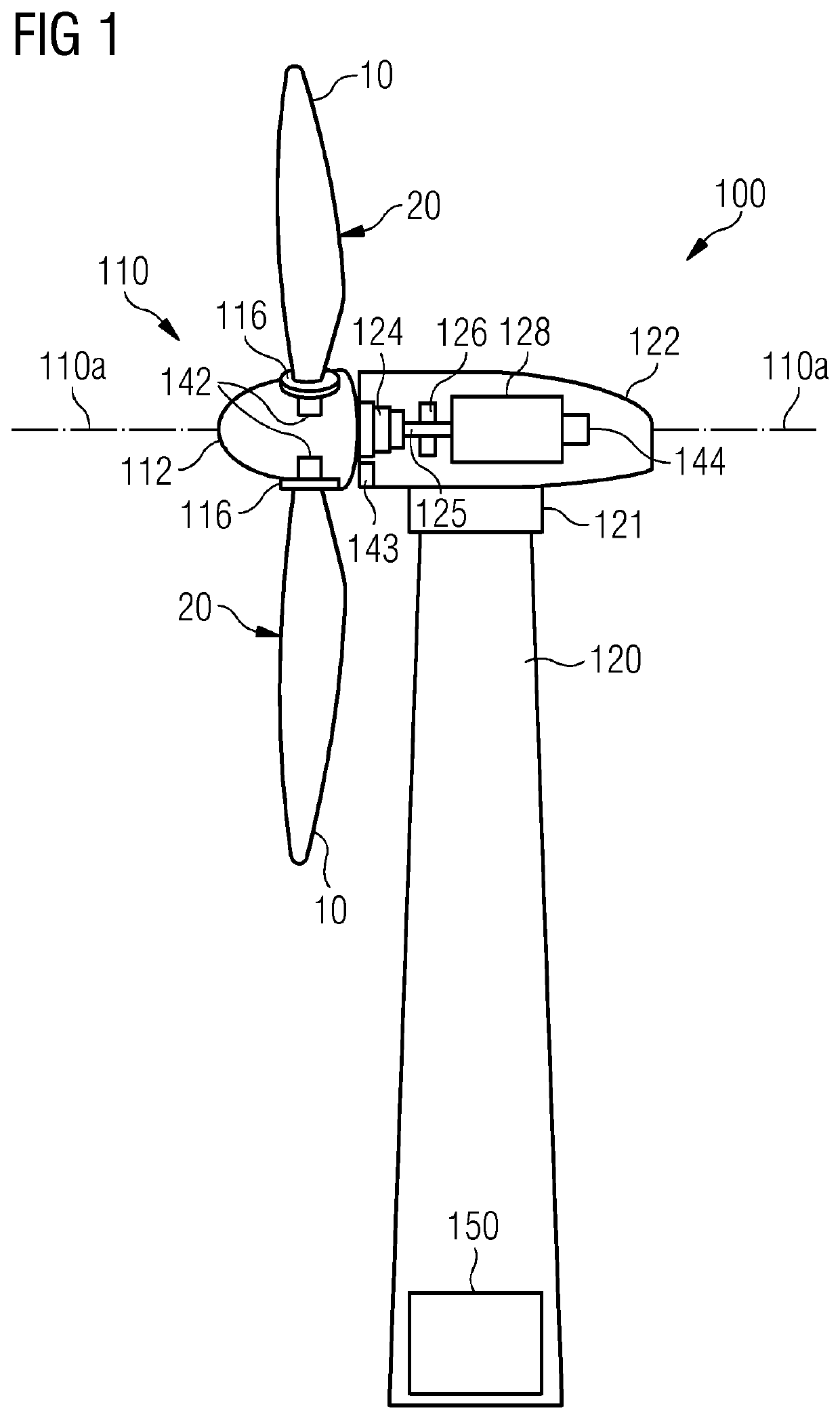
[0031]FIG. 1 shows an exemplary embodiment of a wind turbine 100 of the present technique. The wind turbine 100 includes a tower 120,...


PUM

PropertyMeasurementUnit
thicknessesaaaaaaaaaa
angleaaaaaaaaaa

Abstract

A pultruded fibrous composite strip for wind turbine spar caps, a spar cap having such a strip, and a wind turbine blade having such spar cap. The strip has longitudinally extending unidirectional fibers and an elongate body having first and second edge regions separated in the longitudinal direction of the strip by an intermediate region. The intermediate region has first and second mutually opposed longitudinally extending and parallelly disposed planar surfaces. The strip's thickness is measurable perpendicular to the planar surfaces and the width is measurable parallel to the planar surfaces and perpendicular to the longitudinal direction of the strip. In the strip, the first and / or the second edge regions, starting from the intermediate region and extending longitudinally, simultaneously tapers along the width and the thickness of the strip.

Description

CROSS-REFERENCE TO RELATED APPLICATIONS[0001]This application claims priority to European application No. 18165844.4, having a filing date of Apr. 5, 2018, the entire contents of which are hereby incorporated by reference.FIELD OF TECHNOLOGY[0002]The following relates generally to wind turbines, and in particular, to a spar cap of a wind turbine rotor blade. More specifically, the following relates to pultruded unidirectional fibrous composite strips, spar caps having such pultruded unidirectional fibrous composite strips, and wind turbine blades having spar caps that have such pultruded unidirectional fibrous composite strips.BACKGROUND[0003]Dimensions of wind turbines and wind blades are ever increasing, and consequently are increasing the challenges to overcome during the manufacturing processes of such wind turbine rotor blades. Presently, preferred materials used to manufacture wind turbine rotor blades, hereinafter also referred to as the blades, are glass- and / or carbon-fiber...

Claims


Application Information

Patent Timeline
Patent Type & Authority Patents(United States)
IPC IPC(8): F03D1/06B29C70/52B29D99/00B29L31/08B29C70/20B29C70/30
CPCF03D1/0675B29C70/30B29C70/52B29D99/0028B29C70/20B29L2031/085F05B2230/20F05B2240/301F05B2280/6003B29C70/302Y02E10/72Y02P70/50
Inventor GIROLAMO, DONATO
Owner SIEMENS GAMESA RENEWABLE ENERGY AS
Why Eureka
Try Eureka