Optical projection system and projector including the same
a technology of optical projection system and projector, applied in the field of optical projection system, can solve the problems of affecting the image quality of the image,
- Summary
- Abstract
- Description
- Claims
- Application Information
AI Technical Summary
Benefits of technology
Problems solved by technology
Method used
Image
Examples
first embodiment
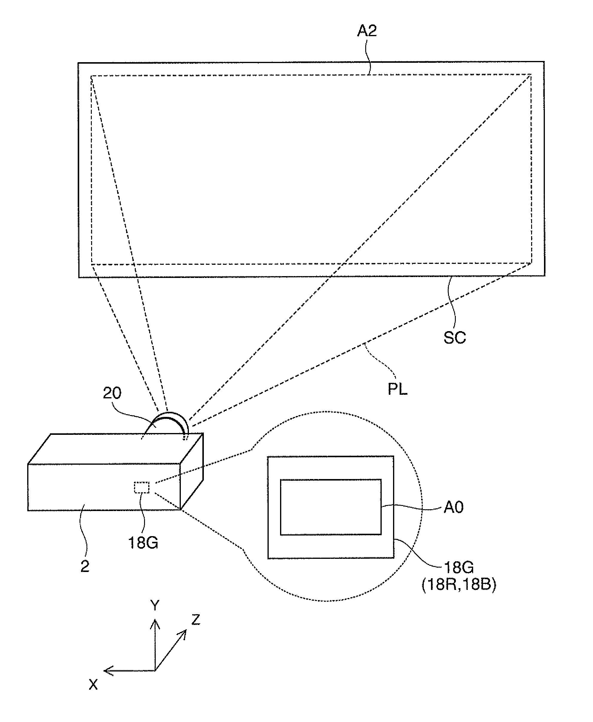
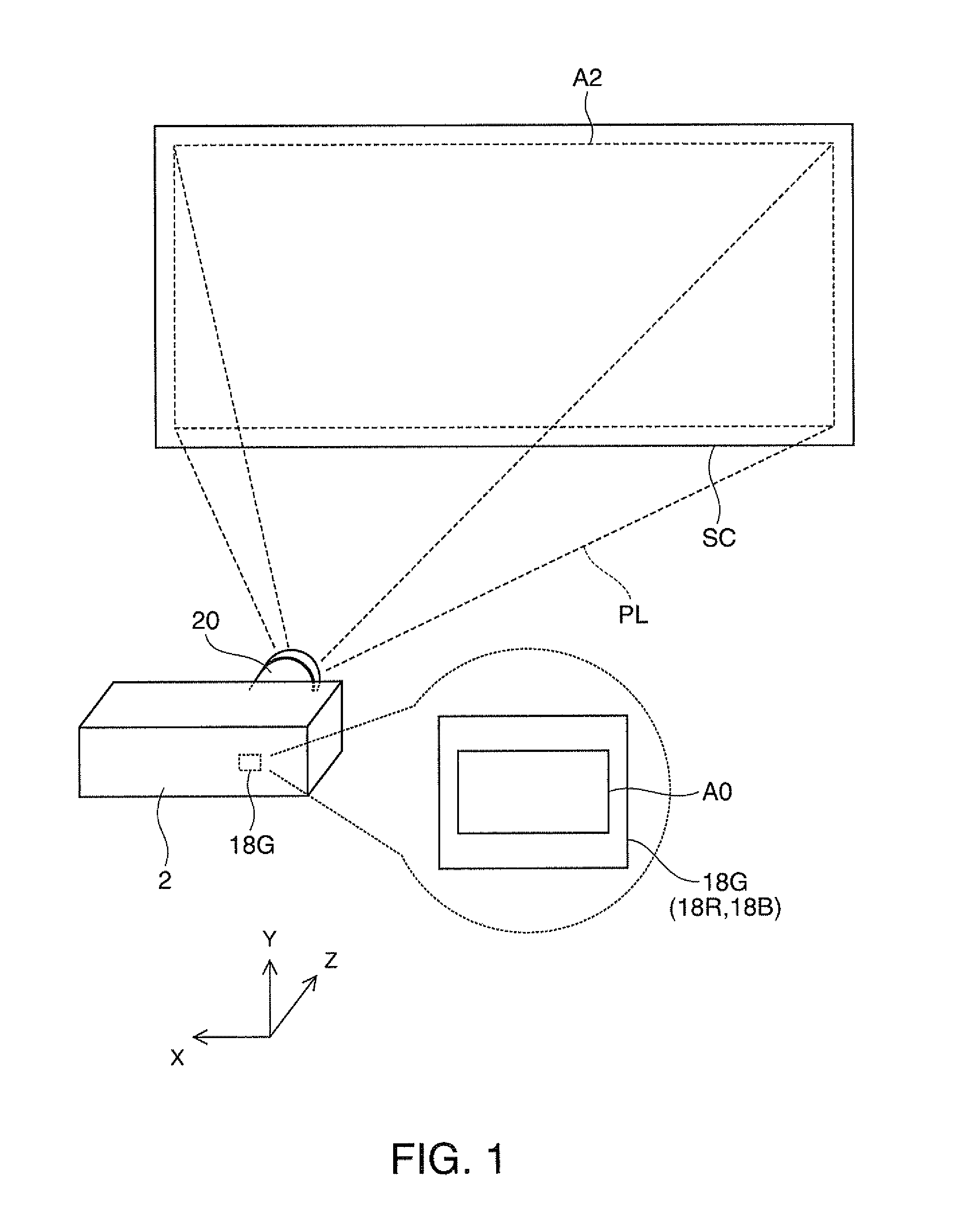
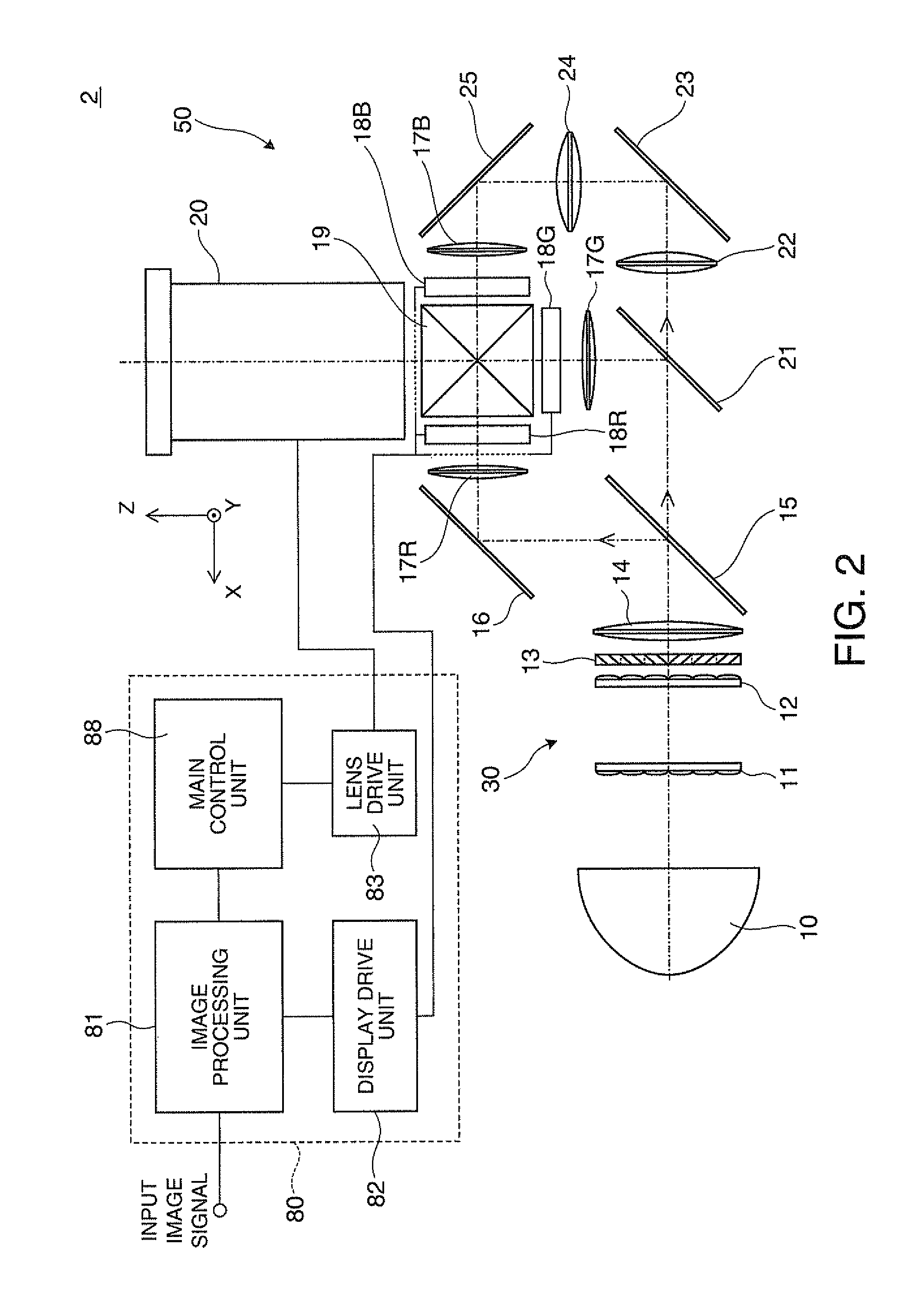
[0047]As shown in FIG. 1, a projector 2 according to a first embodiment of the invention forms image light PL in response to an image signal, and projects the corresponding image light PL on a surface to be projected, such as a screen SC. When the image of a liquid crystal panel 18G (18R, 18B), which is a light modulation device embedded in the projector 2, is enlarged and then projected on the screen (the surface to be projected) SC, the optical projection system 20 of the projector 2 can make the aspect ratio AR0 of the image of the liquid crystal panel 18G (18R, 18B) different from the aspect ratio AR2 of an image to be projected on the screen SC. That is, although the aspect ratio AR0 of the display region A0 of the liquid crystal panel 18G can be different from the aspect ratio AR2 of the display region A2 of the screen SC, the aspect ratio AR0 of the display region A0 of the liquid crystal panel 18G can be equal to the aspect ratio AR2 of the display region A2 of the screen SC...
example 1
[0101]FIGS. 9 and 10 are views illustrating a detailed Example 1 of the optical projection system 20 of the first embodiment, and illustrate the optical projection system 20 in the first operating state. FIG. 9 illustrates the state of a “tele end”, in which magnification power is comparatively low. FIG. 10 illustrates the state of a “wide end”, in which magnification power is comparatively high.
[0102]The optical projection system 20 includes lenses L1 to L19. The first group 30 is configured to include the lenses L1 to L13, the second group 40 is configured to include the lenses L14 to L17, and the third group 60 is configured to include the lenses L18 and L19. The lenses L1 to L13 included in the first group 30 are lenses having rotationally symmetric spherical surfaces around the optical axis OA. In the second group 40, the cemented lenses L14 and L16 are lenses that have positive power with regard to the longitudinal Y direction and cylindrical lenses which do not have power wit...
second embodiment
[0114]Hereinafter, an optical projection system or the like according to a second embodiment will be described. In addition, the embodiment is the modification example of the optical projection system or the like according to the first embodiment, and portions and items which are not especially described are the same as the case of the first embodiment.
[0115]FIGS. 15A and 15B are views illustrating a modification example of an optical projection system 20 shown in FIGS. 4A and 4B. The optical projection system 20 includes a plurality of diaphragms arranged at different positions in the extending direction of the optical axis OA. That is, the optical projection system 20 of the embodiment includes a first diaphragm 170a relatively arranged on the screen side and a second diaphragm 170b arranged in the subject side. The diameter of diaphragms 170a and 170b varies according to the advance and retraction of the second group 40 by the diaphragm drive mechanism 61b (refer to FIG. 3) embed...
PUM
 Abstract
Description
Claims
Application Information
 - R&D
- Intellectual Property
- Life Sciences
- Materials
- Tech Scout
- Unparalleled Data Quality
- Higher Quality Content
- 60% Fewer Hallucinations
Browse by: Latest US Patents, China's latest patents, Technical Efficacy Thesaurus, Application Domain, Technology Topic, Popular Technical Reports.
© 2025 PatSnap. All rights reserved.Legal|Privacy policy|Modern Slavery Act Transparency Statement|Sitemap|About US| Contact US: help@patsnap.com


