Predictive load management system

Inactive Publication Date: 2005-03-31
CATERPILLAR INC
View PDF37 Cites 42 Cited by
  • Summary
  • Abstract
  • Description
  • Claims
  • Application Information

AI Technical Summary

Benefits of technology

In accordance with one aspect of the invention, a predictive load management system includes a power source operable to generate a power output and having a desired operating range. The predictive load management system further includes a transmission having a drive member operably connected with the power source and a driven member. The predictive load management system also includes a control system in communication with the power source and the transmission. The control system is operable to receive at least one

Problems solved by technology

However, due to response delays of the various engine systems and the immediate demand for a change in power, engine speed may either droop under or over shoot a desired engine speed.
A problem common to many known CVT systems is that operation of these devices may produce loads on the engine that are severe enough to cause engine “stalling” or “lugging”, a.k.a., excessive engine speed droop.
“Lugging” or “stalling” the engine may decrease the productivity and efficiency of the engine.
Such CVT systems may

Method used


Image

  • Predictive load management system
  • Predictive load management system
  • Predictive load management system

Examples


Embodiment Construction

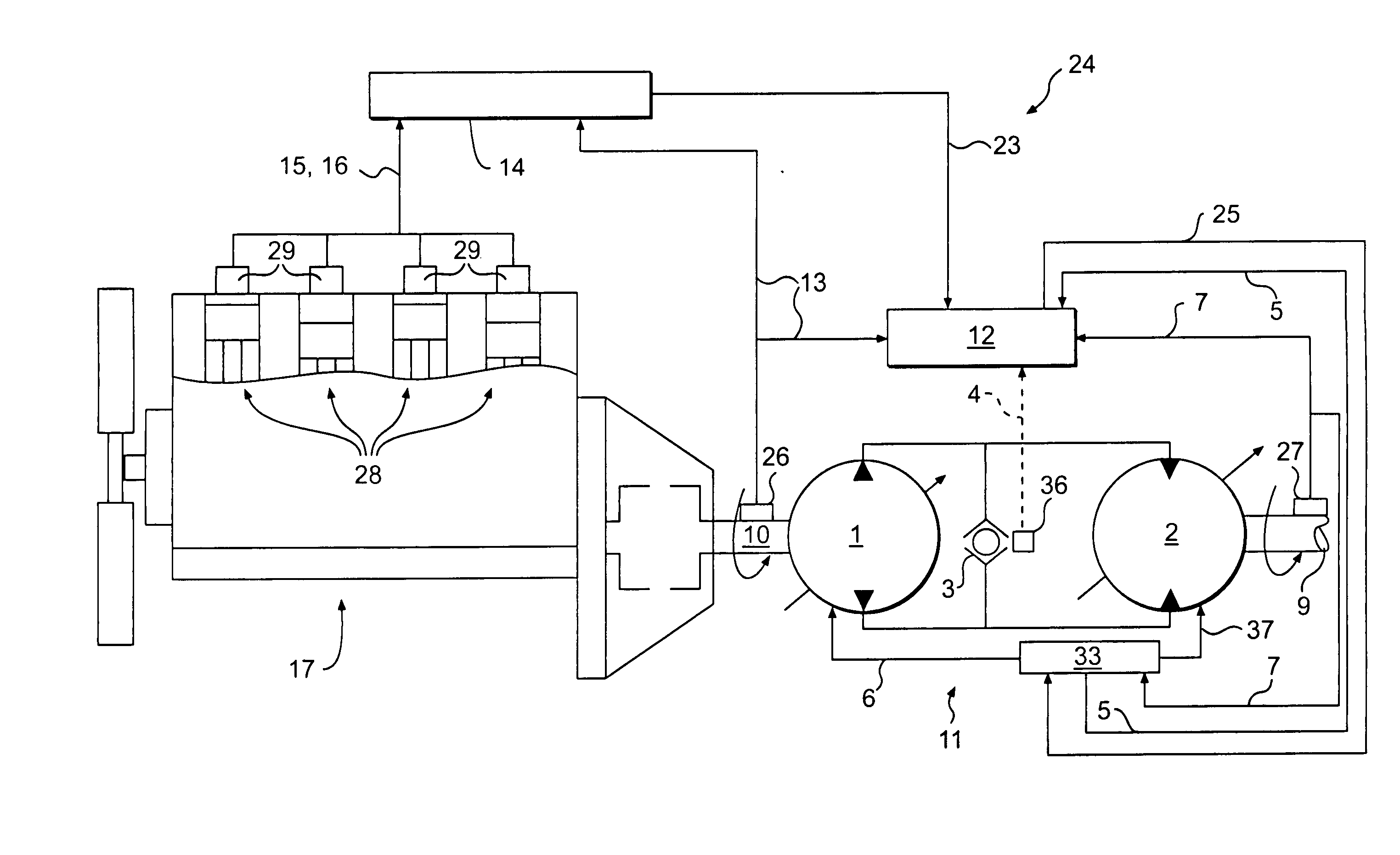
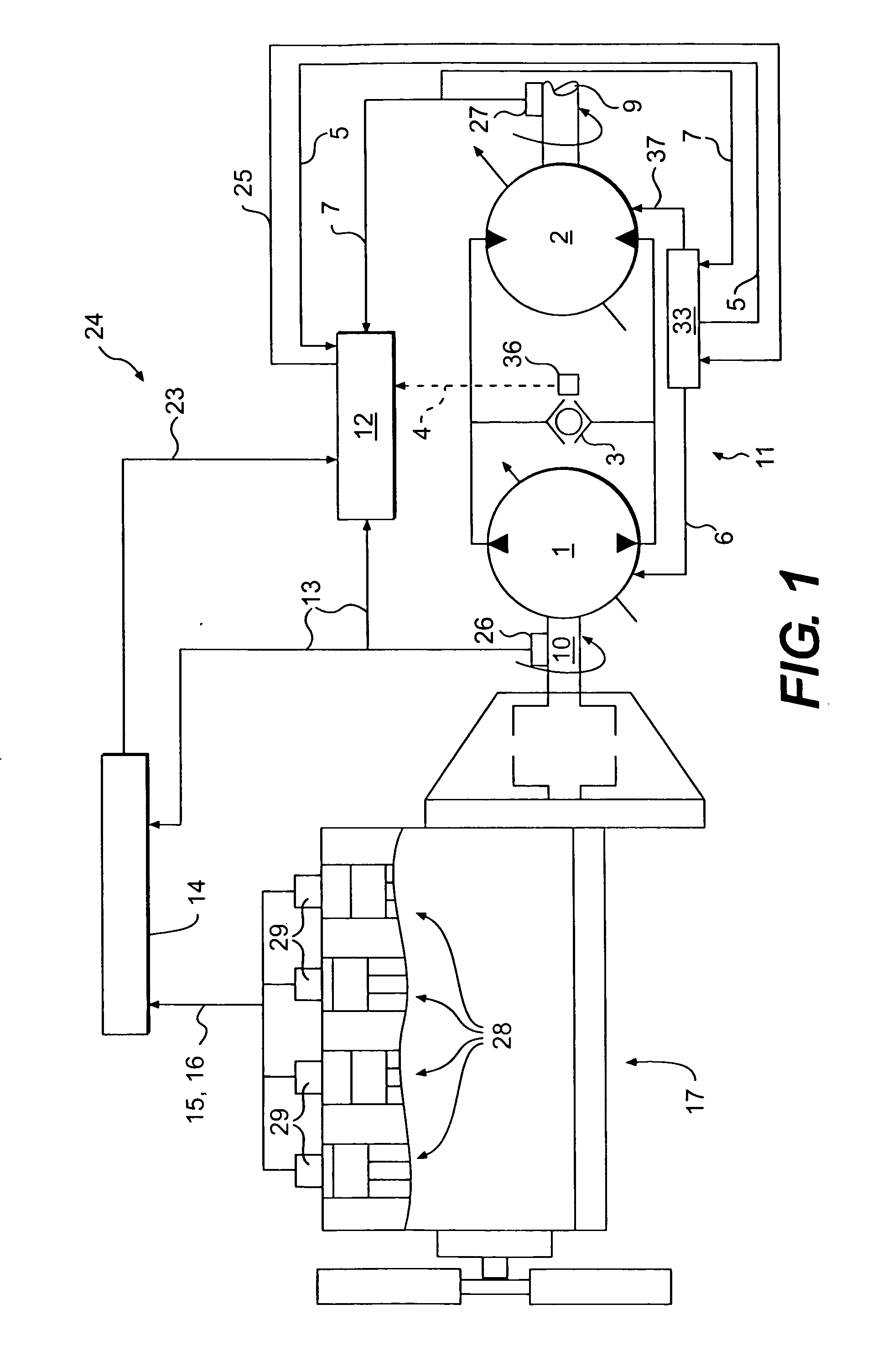
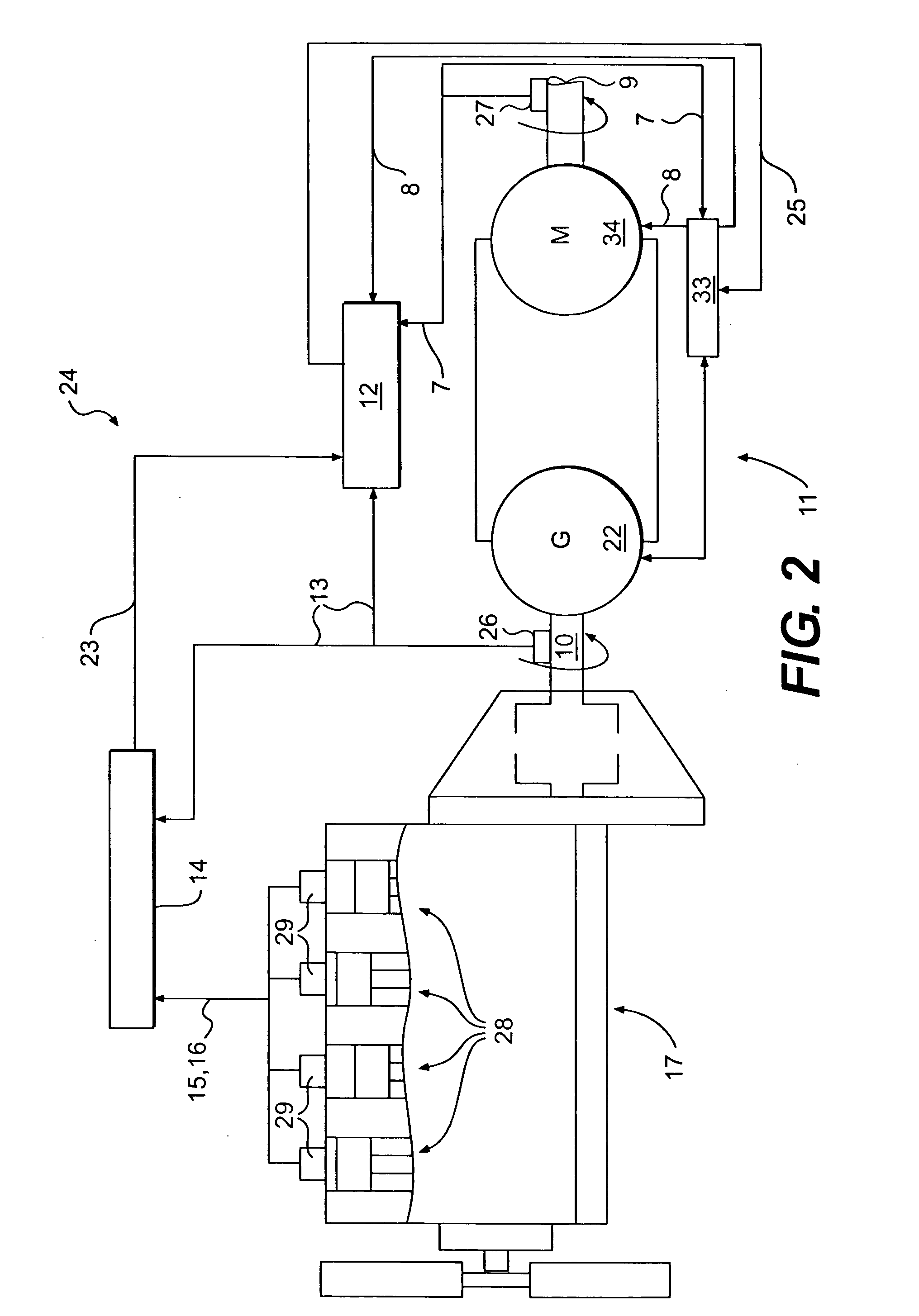
Exemplary embodiments of a predictive load management system are illustrated in FIGS. 1 and 2. The predictive load management system may be used, for example, with a power source 17 and a transmission 11. In the embodiments of FIGS. 1 and 2, power source 17 is an engine, such as an internal combustion engine. The engine may be a diesel engine, a gasoline engine, a natural gas engine, or any other engine readily apparent to one skilled in the art. It is contemplated that the predictive load management system may be used with other types of power sources such as, for example, fuel cells.

As illustrated in FIG. 1, the power source 17 includes a plurality of combustion chambers 28. A fuel injector 29 is associated with each combustion chamber 28. In the illustrated embodiment, the power source 17 includes four combustion chambers 28 and four associated fuel injectors 29. One skilled in the art will readily recognize that power source 17 may include a greater or lesser number of combus...


PUM


Abstract

A predictive load management system is provided. A power source is operable to generate a power output and has a desired operating range. A transmission has a drive member operably engaged with the power source and a driven member. A control system is operable to receive at least one input indicative of a load on the transmission and to identify a desired load of the transmission based on the at least one input. The control system is also operable to receive at least one input indicative of current power output of the power source. The control system limits the desired transmission load applied to the driven member of the transmission based on the current power output of the power source to thereby prevent the power source from operating outside of the desired operating range.

Description

TECHNICAL FIELD This invention relates generally to a load management system and, more particularly, to a system and method for predictive load management. BACKGROUND Work machines such as, for example, wheel loaders, track type tractors, and other types of heavy machinery are used for a variety of tasks. These work machines include a power source, which may be, for example, an engine, such as a diesel engine, gasoline engine, or natural gas engine that provides the power required to complete these tasks. To efficiently perform these tasks, the work machines require a transmission that is capable of transmitting the torque generated by the engine over a wide range of speeds. Typically, work machines use a continuously variable transmission (CVT) to convert engine torque to drive traction devices, such as wheels or tracks that propel the work machine. Continuously variable transmissions are capable of providing a desired output torque at any speed within its operating range by con...

Claims


Application Information

Patent Timeline
IPC IPC(8): B60K6/46B60W10/06B60W10/10B60W30/18F16H61/46F16H61/468G06F19/00
CPCB60K6/46B60W10/06B60W10/103B60W10/105Y10T477/65F16H61/468Y02T10/6217Y02T10/84Y10T477/679B60W30/1884Y02T10/62
Inventor GUVEN, MUSTAFA K.KURAS, BRIAN D.VANDERHAM, MICHAEL E.
Owner CATERPILLAR INC
Why Eureka
Try Eureka