Manual machine for attaching an insulation displacement type connector

a displacement type, man-machine technology, applied in the direction of unstripped conductor connection apparatus, coupling device connection, manufacturing tools, etc., can solve the problems of very complex and unefficient rearrangement of constituent members in such a prior art machin

Inactive Publication Date: 2005-04-07
JST MFG CO LTD
View PDF4 Cites 5 Cited by
  • Summary
  • Abstract
  • Description
  • Claims
  • Application Information

AI Technical Summary

Benefits of technology

[0012] An object of the present invention made in view of this problem is therefore to provide a manual machine for attaching an insulation displacement type connector such that any work for changing or rearranging its parts is not necessitated even when end type harnesses are to be made in place of daisy chain type ones, or vice versa.
[0013] Another object is to protect the insulation displacement type connector from taking any erroneous or wrong position when a sure and reliable electric connection is established using such a manual machine.
[0015] Preferably, the collision portion may be formed as an array of flat wall zones of a front face of the wire stopper. Each wall zone is defined between adjacent two of notches carved side by side at the given pitch in the front face. This feature will enable a surer positioning of the wire free ends.
[0017] In operation, the wire stopper pivoted to the set block will swing between its active and idle positions, towards or away from the set block. Any parts need no longer be changed or rearranged when manufacture of end type harnesses is switched over to manufacture of daisy chain harnesses, or vice versa, affording efficient production thereof The free ends of electric wires forming an end type harness will merely be pushed to the collision portion of wire stopper then taking its active position, without trimming and aligning said free ends of the wires prior to insulation displacement attachment to a connector. However in case of making a daisy chain harness, the wire stopper is retracted to its idle position before the wire holder will guide and hold the wires side by side at a given pitch. Subsequent to this step, the wire stopper will be shifted to its active position where its biasing portion urges the middle portions of said wires towards the set block. Thus, the connector can efficiently be attached to the wire middle portions in the manner of insulation displacement.

Problems solved by technology

In addition, the stopping plate 24 should also be dismounted or remounted, thus rendering very intricate and unefficient the rearrangement of constituent members in such a prior art machine.

Method used


Image

  • Manual machine for attaching an insulation displacement type connector
  • Manual machine for attaching an insulation displacement type connector
  • Manual machine for attaching an insulation displacement type connector

Examples


Embodiment Construction

[0042] Now an embodiment of the present invention will be described referring to the accompanying drawings.

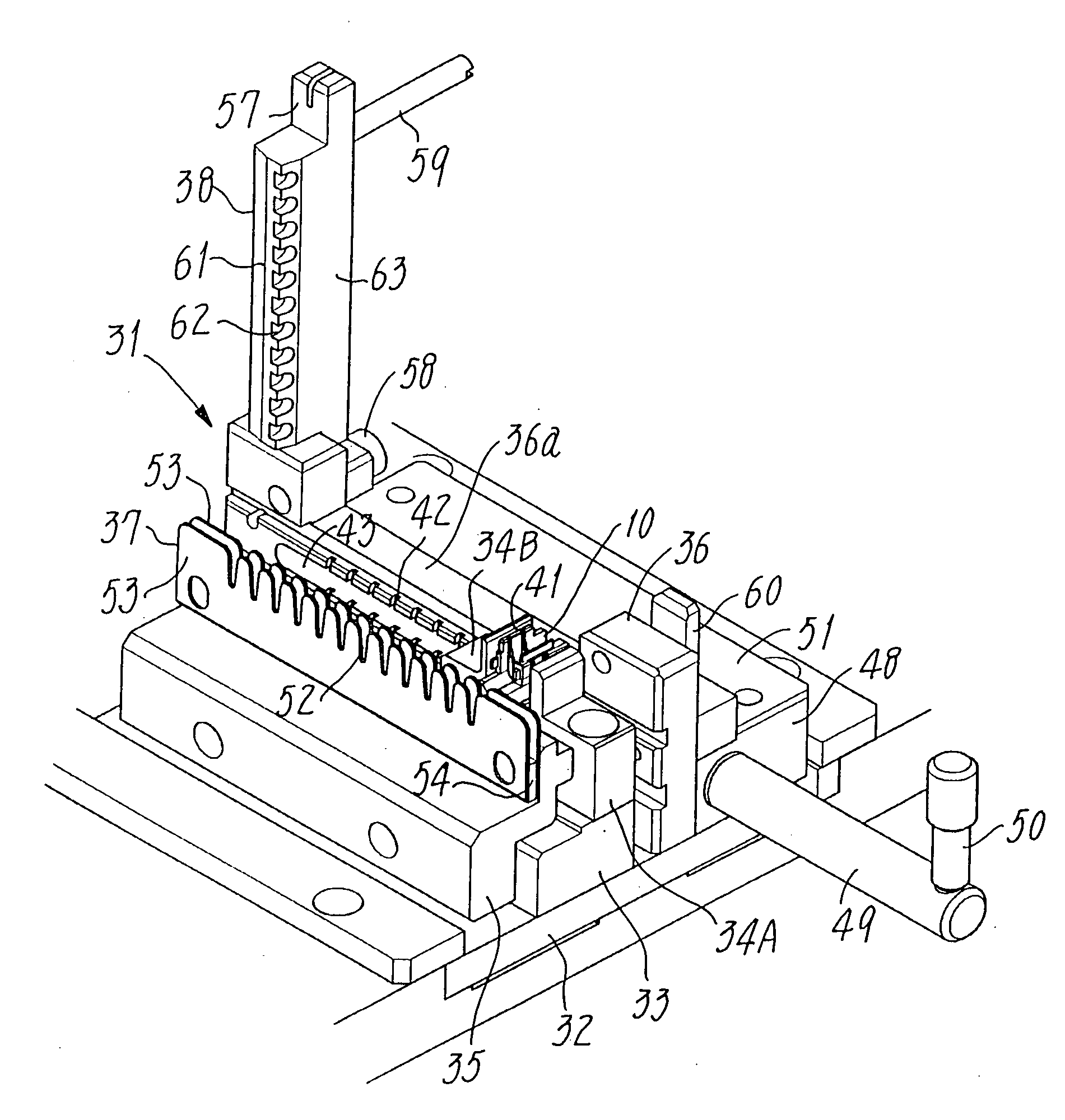
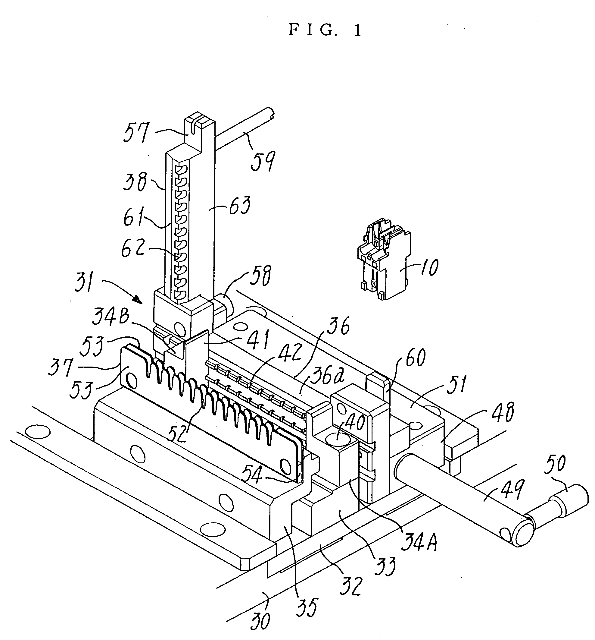
[0043]FIG. 1 shows the machine body 30 of a manual machine for attaching to wires an insulation displacement type connector. A connector positioning device 31 mounted on the machine body is in its inoperative home position, ready to start to position the wires 11 relative to the connector 10. The machine body 30 comprises a pneumatic press or a hand press not detailed here but driving a punch 25 (see FIGS. 7(a) to 7(c)) up and down at a working position of said device.

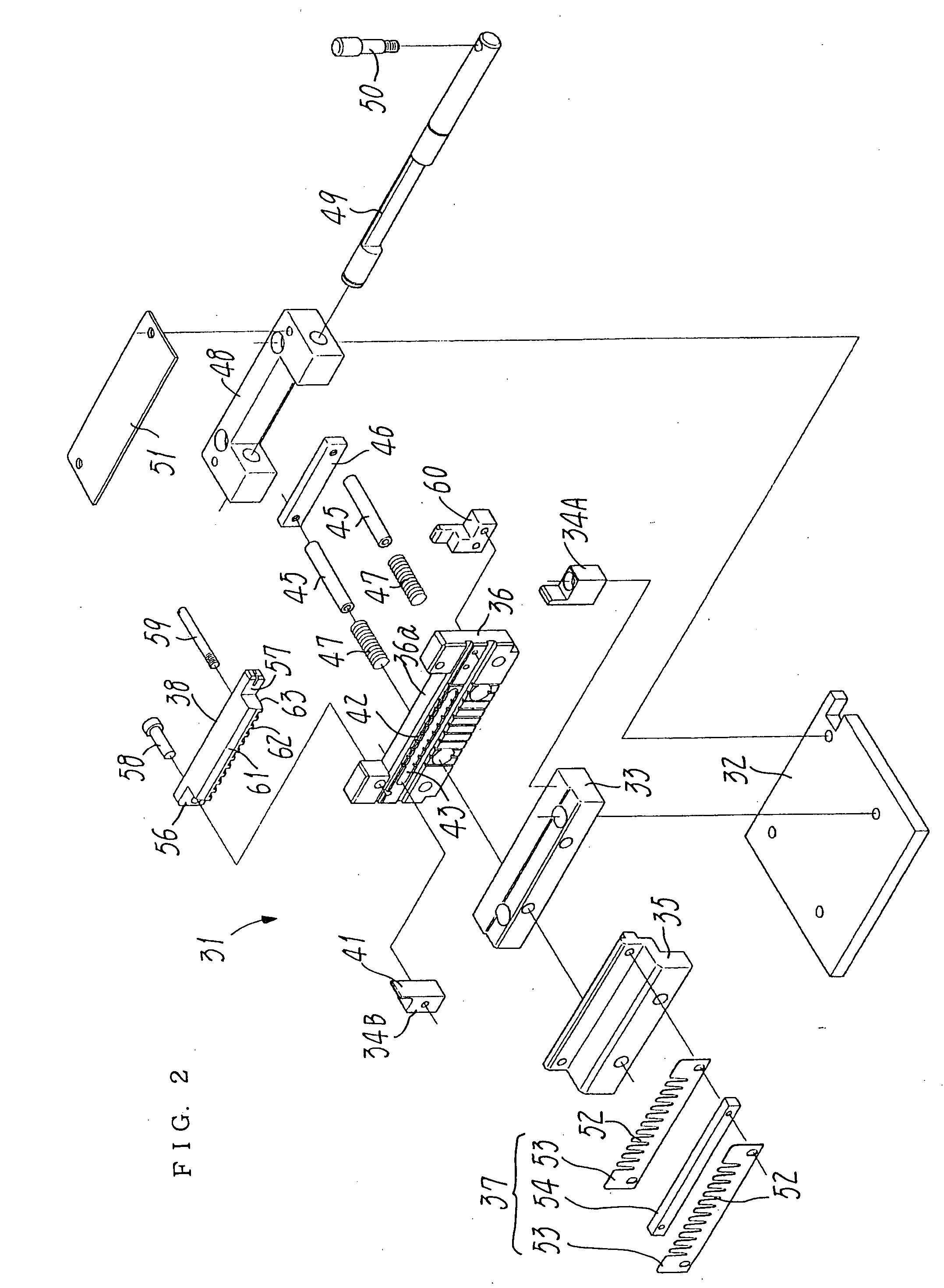
[0044] As shown in an exploded state in FIG. 2, the positioning device 31 mounted on the machine body 30 is capable of sliding thereon. This device 31 comprises a base plate 32 movable between its inoperative home position and its working position, a connector rest 33 fixed on the base plate, and a pair of shoes 34A and 34B of a housing stopper for positioning the connector lying on the rest 33. The positioning ...


PUM

PropertyMeasurementUnit
angleaaaaaaaaaa
insulation displacementaaaaaaaaaa
distanceaaaaaaaaaa

Abstract

A manual machine for attaching an insulation displacement connector (10) has housing stoppers (34A,34B) for positioning it on a rest (33), a housing holder (35) for holding the connector on the rest, and a set block (36) disposed near the rest in order to position electric wires (11) at their ends or middle portions. The machine further has a wire holder (37) near the housing holder (35) so as to guide and hold the wires at a given pitch, and a wire stopper (38) pivoted to the set block (36) so as to swivel between an active position close to this block and an idle position remote from it. The wire stopper (38) has a collision portion (61) on which the wire ends (11) will impinge to be aligned one with another, and a biasing portion (63) that will urge the wires' middle portions towards the set block (36).

Description

FIELD OF THE INVENTION [0001] The present invention relates to a manual machine for attaching an insulation displacement type connector to portions of a plurality of electric wires so as to form a wire harness, and more particularly relates to such a machine that an operator will manually place in a body of said machine both the wire portions and the connector, in order to subsequently establish an electric connection between said wires and said connector. PRIOR ART [0002] Wire harnesses of this structure are classified into the end type and the daisy chain type. Each insulation displacement type connector forming the end type harnesses is fixed on either or both of opposite wire ends. In contrast, each daisy chain type harness comprises a plurality of such connectors all secured to middle portions intermediate between the wire ends. Certain manual machines known in the art are useable to manufacture any harnesses, whether end type or daisy chain type. [0003]FIGS. 12 and 13 shows on...

Claims


Application Information

Patent Timeline
Patent Type & Authority Applications(United States)
IPC IPC(8): H01B13/012H01R43/01
CPCH01R43/015Y10T29/53252Y10T29/53226Y10T29/53213Y10T29/53243Y10T29/49174Y10T29/53217Y10T29/53209
Inventor KINOSHITA, KEIICHIYAMANAKA, KAZUYUKI
Owner JST MFG CO LTD
Why Eureka
Try Eureka