Washing machine

a washing machine and washing machine technology, applied in other washing machines, cleaning using liquids, textiles and paper, etc., can solve the problems of heavy burden on the user's body, cuffs, collars, stained parts, and inability to clean satisfactorily with all-together washing, etc., to achieve high washing effect, transmit supersonic waves efficiently, and avoid damage to laundry

Inactive Publication Date: 2005-04-07
SHARP KK
View PDF12 Cites 117 Cited by
  • Summary
  • Abstract
  • Description
  • Claims
  • Application Information

AI Technical Summary

Benefits of technology

[0044] In the washing machine structured as described above, the partial washing apparatus performs supersonic washing by using a supersonic vibration device. With this structure, it is possible to cope with stubborn stains without damaging laundry.
[0045] In the washing machine structured as described above, the supersonic vibration device is composed of a vibration horn coupled to a resonator, a head portion for producing supersonic waves is provided at one end of the vibration horn, and, while vibration is transmitted from the resonator to the head portion, the transmission direction of the vibration is turned substantially perpendicularly. With this structure, even when the supersonic vibration device is housed in the partial washing apparatus that rotates in a horizontal plane, it is possible to make supersonic waves act on the washing por

Problems solved by technology

However, heavily dirtied parts of laundry, for example collars, cuffs, and stained parts, often cannot be cleaned satisfactorily with all-together washing as described above.
This causes the dirt and detergent components left in the laundry to be released into the rinsing water.
This puts a heavy burden on the user's body, producing severe fatigue.
However, this increases the height of the main body of the washing machine, bringing the laundry entrance to a higher position, and thus makes it difficult to put in

Method used


Image

  • Washing machine
  • Washing machine
  • Washing machine

Examples


first embodiment

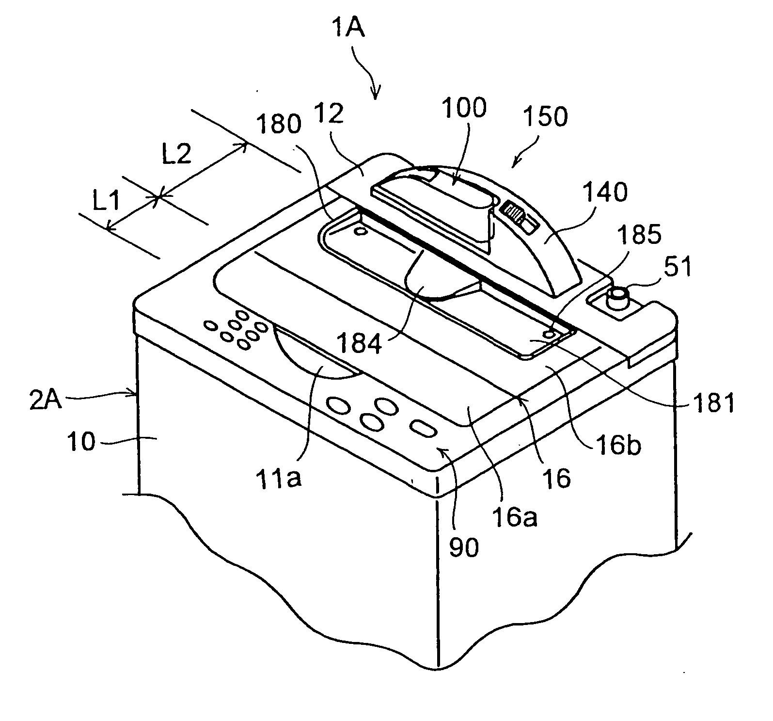
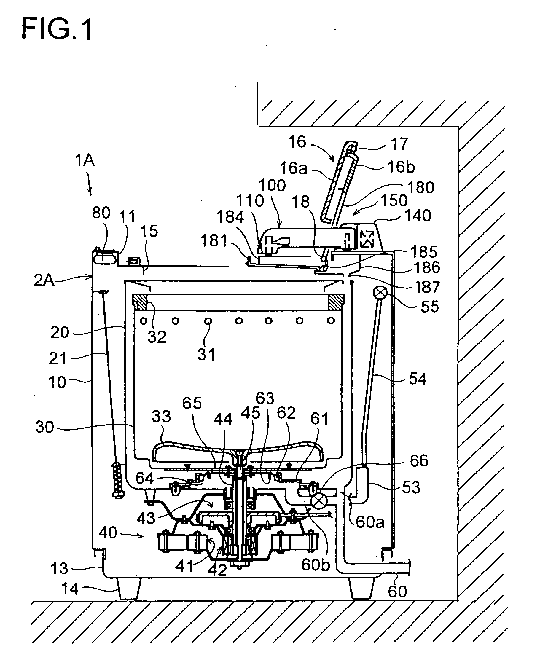
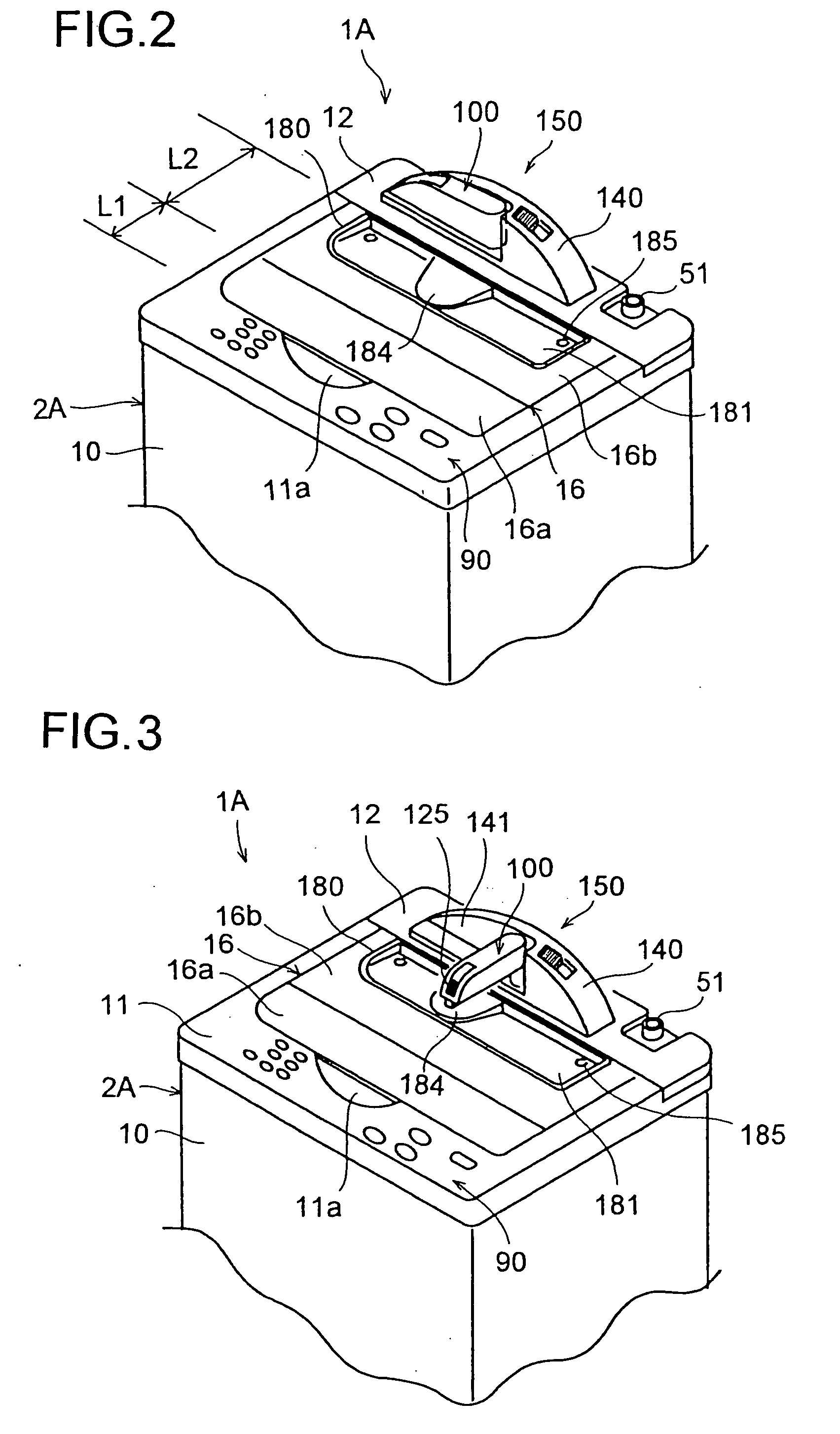
[0071] The washing machine 1A of the first embodiment differs from the washing machine 1 shown in FIGS. 21 and 22 in that a partial washing apparatus 100 is fitted on the outer surface of the main unit 2A. The partial washing apparatus 100 has a base 140. The base 140 and the partial washing apparatus 100 are assembled into a unit 150, which is fitted on the top surface of the back panel 12. Now, the structure of the unit 150 will be described with reference mainly to FIGS. 6 to 13.

[0072] The base 140, when viewed from the front, has the shape of a segment of a circle, with the top surface of the base 140 describing the arc and the bottom surface the chord. The base 140 is molded out of synthetic resin into a shape having a predetermined thickness in the depth direction. The base 140 has a recess 141 formed in the left half of a front portion thereof to accommodate the partial washing apparatus 100. At the right end of the recess 141, a hollow support shaft 142 is formed to extend v...

second embodiment

[0141]FIG. 20 shows the washing machine of the present invention. The washing machine 1B shown here incorporates a so-called tumbler-type washing tub that rotates about a horizontal axis. A door 220 is provided in the front face of a main unit 2B, and laundry is put in the washing tub (not shown) with the door 200 open. An operation panel 90 is provided in a front portion of the top face of the main unit 2B, just as in the washing machine 1A of the fist embodiment.

[0142] In the washing machine 1B of the second embodiment, a sink 230 is formed in a top plate 11 of the main unit 2B, and a partial washing apparatus 100 is arranged in the sink 230. The partial washing apparatus 100 is of a fixed type. On the bottom surface of the sink 230, a stage 231 is formed so as to face the partial washing apparatus 100, and drain outlets 232 are formed in the lowest portions thereof on both sides of the stage 231. A lid 233 that can be opened and closed freely is provided so as to cover the sink 2...


PUM


Abstract

A washing machine has a partial washing apparatus fitted on an outer surface of a main unit having a washing tub housed therein. The partial washing apparatus is movable between an use position and a non-use position. When the partial washing apparatus is in the use position, its washing portion faces a laundry entrance from outside the main unit; when the partial washing apparatus is in the non-use position, its washing portion is retracted from the position in which it faces the laundry entrance. The washing portion achieves washing by using supersonic waves generated by a supersonic vibration device. The laundry entrance is covered with a lid composed of a front lid and a rear lid coupled together so as to be foldable in two. The rear lid has a gate opening formed therein to let the partial washing apparatus pass through. The gate opening is partially or completely closed by a tray for sustaining a piece of laundry. The tray has a drain outlet formed in its bottom surface, and the drain outlet is open toward or communicates with a drain path leading to outside the washing machine. When the partial washing apparatus is in the non-use position, the tray rotates together with the rear lid.

Description

TECHNICAL FIELD [0001] The present invention relates to a washing machine for washing clothes and other articles of cloth. BACKGROUND ART [0002] With a washing machine (electric washing machine), washing is typically achieved by putting pieces of laundry in a washing tub and making them flow together with water having detergent dissolved in it (so as to form them into a whirling stream, or agitate them) inside the washing tub. Alternatively, washing is achieved by rotating the washing tub itself. In either way, the articles put in the washing tub are washed all together so that the effect of washing is exerted uniformly on every part of the laundry. However, heavily dirtied parts of laundry, for example collars, cuffs, and stained parts, often cannot be cleaned satisfactorily with all-together washing as described above. In such cases, particularly dirty parts of laundry need to be washed separately by hand. [0003] For this reason, attempts have been made to equip a washing machine ...

Claims


Application Information

Patent Timeline
IPC IPC(8): D06F19/00D06F39/00D06F37/18D06F37/42D06F39/14
CPCD06F19/00D06F39/14D06F37/42D06F37/18D06F2105/44D06F34/20D06F2103/40
Inventor RYOHKE, HIDEYUKIMATSUMOTO, NOBUHIROHAYASHI, TAKAHIKOSATOH, MASAHIRO
Owner SHARP KK
Why Eureka
Try Eureka