Pressure sensor

Inactive Publication Date: 2005-04-07
CTS CORP ELKHART
View PDF21 Cites 10 Cited by
  • Summary
  • Abstract
  • Description
  • Claims
  • Application Information

AI Technical Summary

Benefits of technology

[0005] In one embodiment of the present invention it is a feature to provide a pressure sensor assembly for attachment to a pressure vessel that includes a high pressure side and a low pressure side. An aperture may be located in at least a portion of the sensor assembly and a seal is located in the aperture. The seal seals the high pressure side from the low pressure side. Electrical leads extend thr

Problems solved by technology

The diaphragms are subject to mechanical fatigue and therefore limit the service life of conventional high pressure sensors.

Method used


Image

  • Pressure sensor
  • Pressure sensor
  • Pressure sensor

Examples


second embodiment

[0049] Second Embodiment

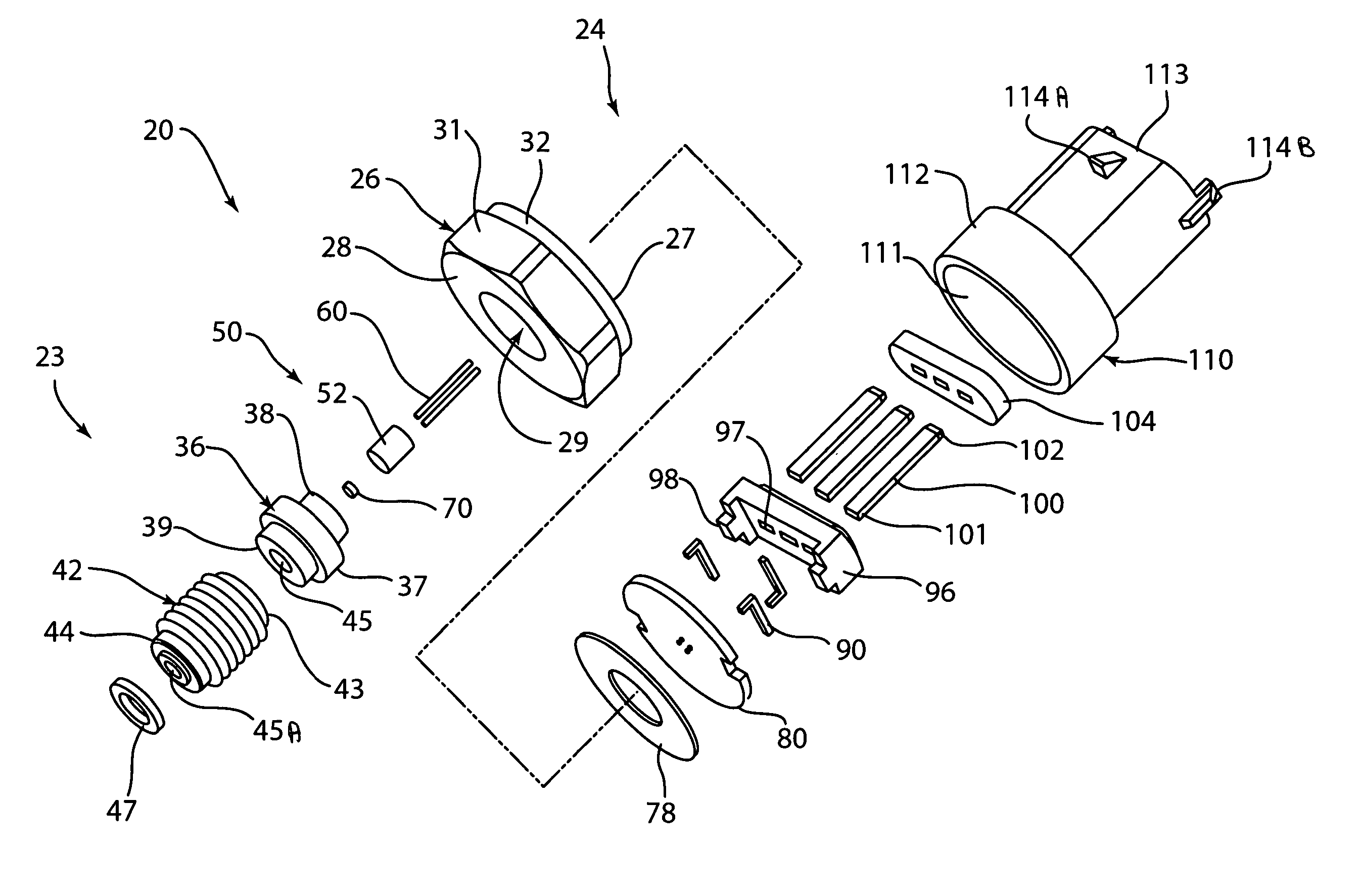
[0050] Referring to FIG. 8, another embodiment of a pressure sensor assembly 200 is shown. Pressure sensor assembly 200 has a housing 202. Housing 202 has a high pressure side 250 and a low pressure side 251. Housing 202 is formed from a unitary piece of stainless steel. Housing 202 has threads 204, flat surfaces 205, a cavity 206 and bores 207. Each bore 207 has a step portion 208.

[0051] A glass insert 220 is located inside of each bore 207 and extends up to step portion 208. Each glass insert 220 has a hole 221 extending through the center. Glass inserts 220 are sintered to make a bond with the surface of the corresponding bore 207. A portion of bores 207 above step portions 208 is not filled with glass insert 220.

[0052] Metal pins 210 are located in corresponding holes 221 and bores 207. Pins 210 each have ends 211 and 212 and a header 214. Each header 214 rests on the corresponding glass insert 220. Pins 210 would typically be gold plated. Pins 210 are ...

third embodiment

[0061] Third Embodiment

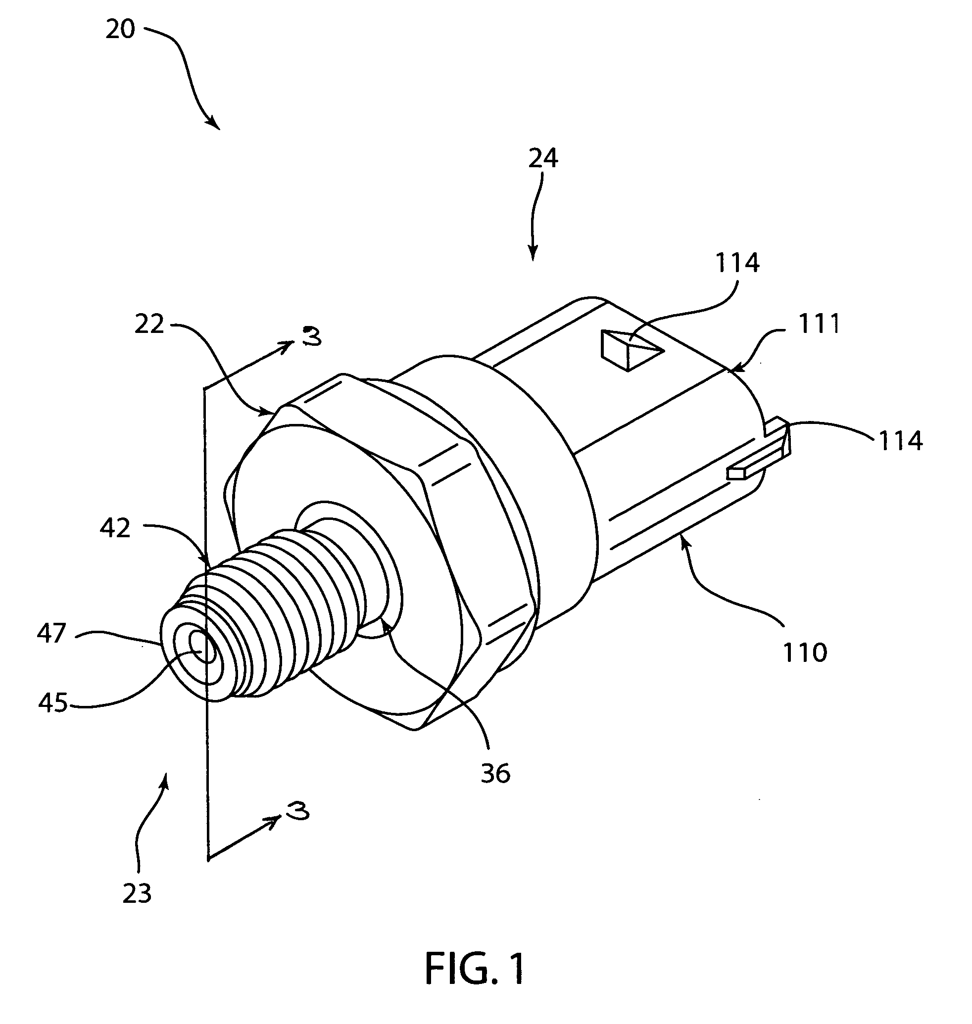
[0062] Referring to FIG. 9, another embodiment of a pressure sensor assembly 300 is shown. Pressure sensor assembly 300 has a high pressure side 323 and a low pressure side 324, and includes a hexagonal portion 326, a threaded portion 336 and a connector shroud 394. Hexagonal portion 326 has flat surfaces 329, a cavity 327 and a hole 328. Threaded portion 336 has a rim 337, ends 338 and 339, a bore 345, a step 346 and a cavity 347. Hexagonal portion 326 and threaded portion 336 are formed from stainless steel. Threaded portion 336 is mounted into hole 328. Rim 339 is welded to hexagonal portion 326.

[0063] A glass insert assembly 350 is located inside of cavity 347. Glass insert assembly 350 has a glass insert 352, metal pins 360 and a sensor 370. Glass insert 352 has holes 356 extending through the center. The outer surface of the glass insert makes a bond to the surface of cavity 347 when sintered.

[0064] Metal pins 360 are located in holes 356. Pins 360 ext...


PUM


Abstract

A pressure sensor for sensing a pressure level of a pressurized medium. In one embodiment, the pressure sensor has a high pressure side and a low pressure side. An aperture may extend through at least a portion of the sensor assembly, and a seal is located in the aperture. The seal seals the high pressure side from the low pressure side. Electrical leads extend through the seal between the high pressure side and the low pressure side. A substrate is located on the high pressure side. A pressure sensitive resistor is mounted on the substrate such that the resistor is directly exposed to the pressurized medium. The resistor changes resistance in response to a change in pressure. The resistor is connected to the electrical leads.

Description

PRIORITY [0001] This application claims priority from U.S. Provisional Patent Application No. 60 / 509,287, filed Oct. 7, 2003, the entirety of which is incorporated by reference.BACKGROUND [0002] The present invention relates to pressure sensors in general and in particular to a pressure sensor that eliminates the use of a diaphragm between the sensor and pressure to be measured. [0003] Conventional devices for high pressure measurement in severe environments rely on a diaphragm in conjunction with a pressure sensing element. Various pressure sensing elements have been used such as strain gages, piezoresistive devices and semiconductor based sensing elements. These devices are constructed such that the diaphragm is positioned between the pressurized process media and the pressure sensing element. The diaphragms are subject to mechanical fatigue and therefore limit the service life of conventional high pressure sensors. A diaphragm free high pressure sensor as presented herein is ther...

Claims


Application Information

Patent Timeline
IPC IPC(8): G01L9/00G01L23/18
CPCG01L9/0052G01L19/003G01L23/18G01L19/0084G01L19/148G01L19/0061
Inventor ERNSBERGER, CRAIGLANGHORN, JASON
Owner CTS CORP ELKHART
Why Eureka
Try Eureka