Method for SAR processing without INS data

Inactive Publication Date: 2005-04-07
OL SECURITY LIABILITY CO
View PDF10 Cites 25 Cited by
  • Summary
  • Abstract
  • Description
  • Claims
  • Application Information

AI Technical Summary

Benefits of technology

The present invention avoids the need for an INS / GPS by focusing a SAR image having discernible features and a center. The image is formed from digitized returns, each of said digitized returns having a phase and an amplitude. The returns are generated from separate pulses transmitted from a plurality of locations.
A range pre-filter / decimation is optionally applied to the coarse image obtained from said motion compensating step as well as an azimuth pre-filter / decimation to reduce the data rate.

Problems solved by technology

The INS / GPS is disadvantageous.
An INS / GPS is an expensive, heavy and computationally burdensome item, comprising accelerometers as well as acceleration / velocity integrating means to ascertain moving platform location as a function of time.
The INS / GPS presents a computationally intensive requirement of time stamping each individual radar return.
The need for a INS / GPS remained, along with its expense, and contribution to reduced SAR radar reliability and increased complexity.

Method used


Image

  • Method for SAR processing without INS data
  • Method for SAR processing without INS data
  • Method for SAR processing without INS data

Examples


Embodiment Construction

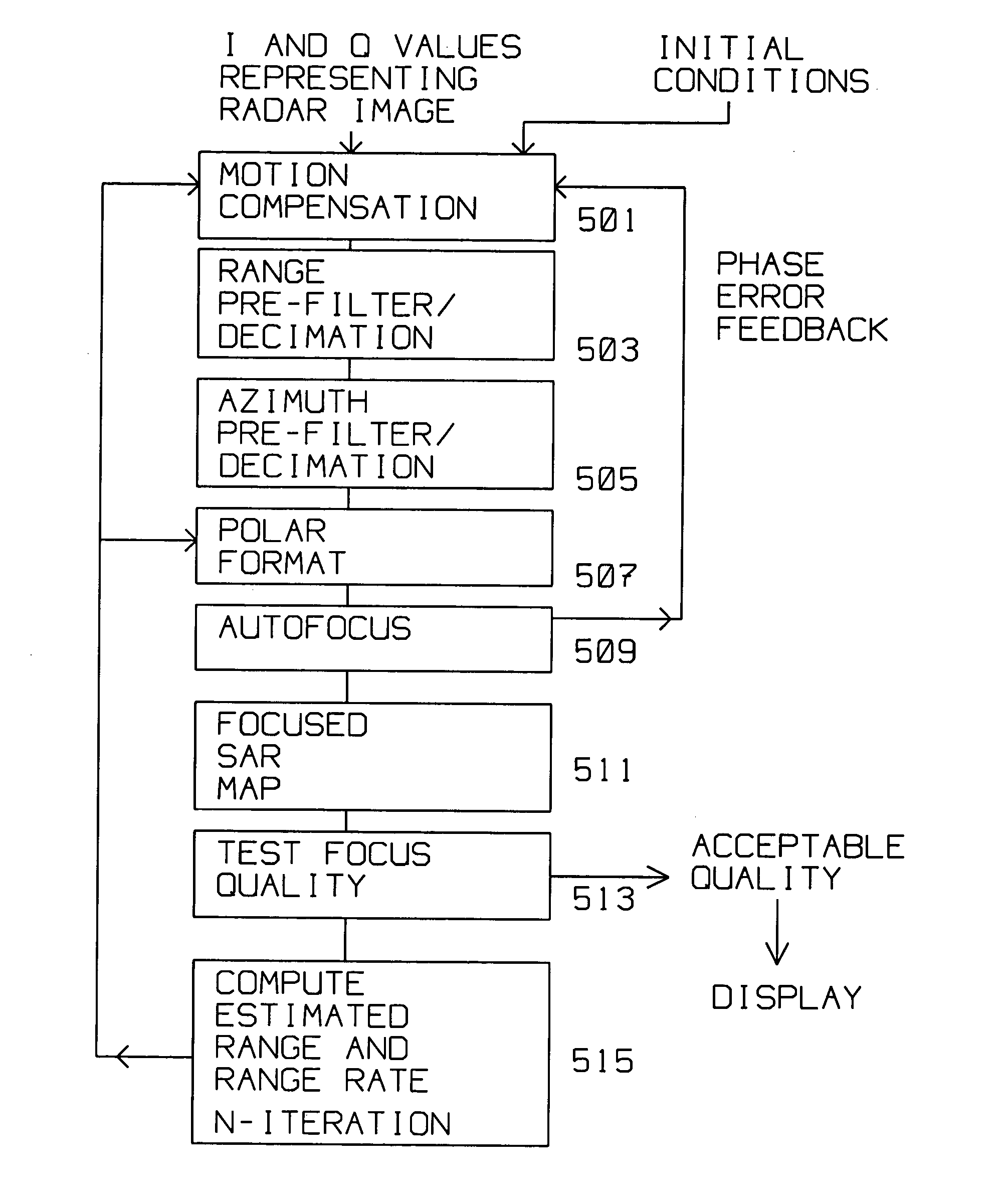
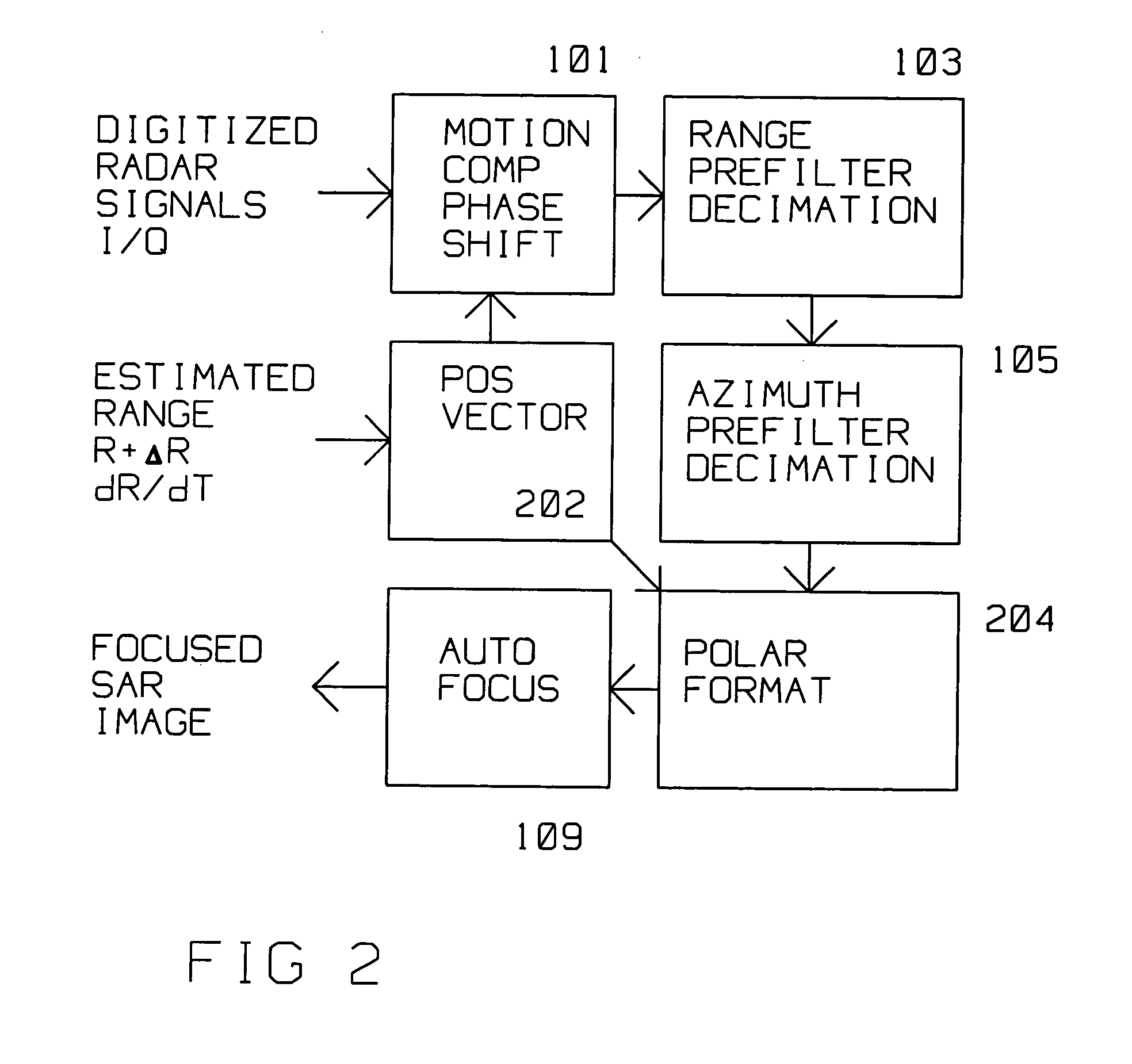
The present invention describes an apparatus and method of focusing SAR images without the use of inertial navigation system / Ground Position Satellite system (INS / GPS) moving platform motion information.

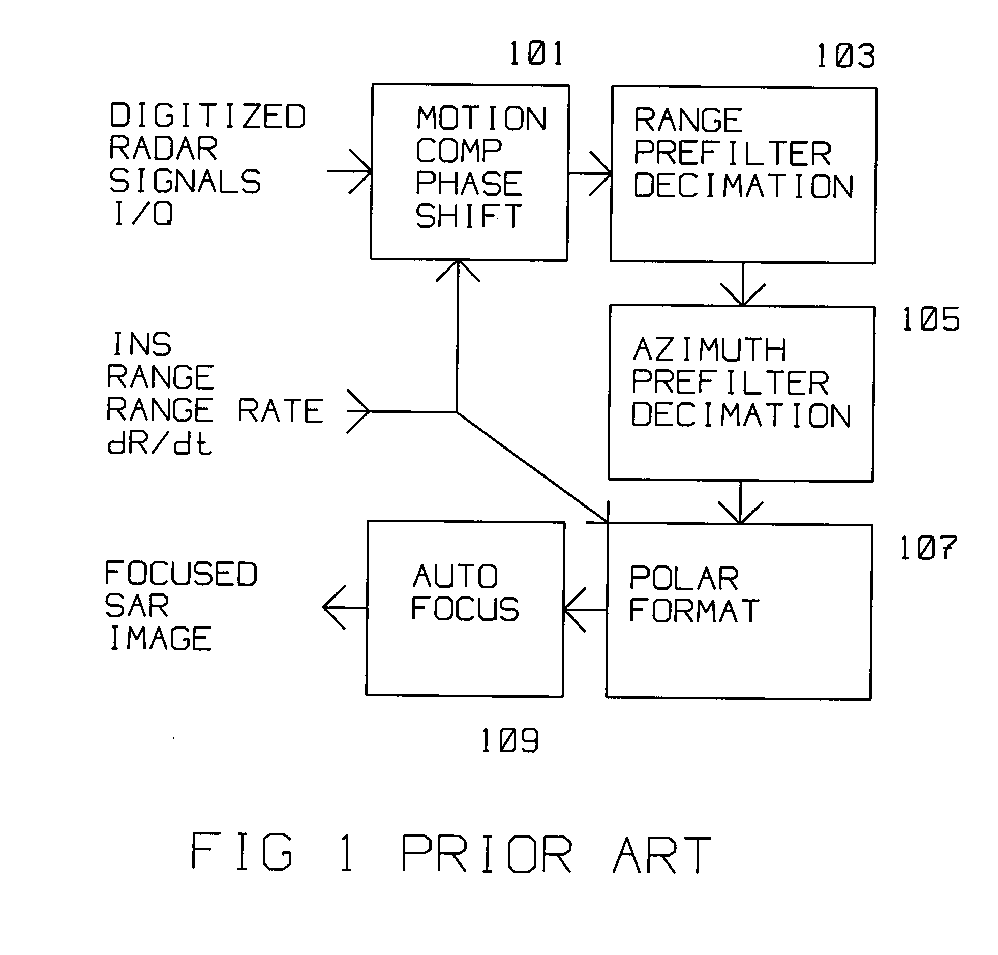
FIG. 1 shows the prior art approach to generating an focused SAR image. Digitized radar signals (the I and Q components) are phase shifted by motion compensation 101. This motion compensation is required to reduce phase errors to the point where known autofocus algorithms can function well, and reduce the phase errors further. Motion compensation 101 adjusts the starting phase and frequency of returned pulses in response to the changing range such that the phase of the returned pulse at the image center remains constant. Motion compensation 101 uses range and range rate information computed from the INS / GPS data. Typically, range pre-filter 103 with (optional) decimation and azimuth pre-filter 105 with (optional) decimation process the motion compensated raw data. Decimation is app...


PUM


Abstract

A SAR radar avoids the need for an INS / GPS by focusing a SAR image having discernible features and a center. The image is formed from digitized returns, each of said digitized returns having a phase and an amplitude. The focusing steps are: storing digitized returns acquired in an azimuth and a range coordinate system; searching within said memory for returns descriptive of the features; computing a coarse range and coarse range rate of the center of said image from the change in position of the features within the azimuth and range coordinate system; motion compensating the digitized returns forming the image using the coarse range and coarse range rate to form a coarse image; converting the digitized returns in polar format into an orthogonal Cartesian coordinate system where the digitized returns are adjusted in phase and amplitude to form an evenly spaced image data; autofocusing the evenly spaced image data to obtain a focused image; performing a two dimensional Fourier transform to obtain a focused image described by the returns; testing the focused image for a focus quality computing an estimated (fine) range and (fine) range rate from features contained within the focused image; converting the fine range and fine range rate within the orthogonal Cartesian coordinate system for use within the azimuth and range coordinate system and motion compensating the digitized returns; iterating the motion compensating step and subsequent steps using the fine range and the fine range rate until the attributes of focus quality reach a predefined level. The autofocus step generates a phase error, said phase error is converted to an adjustment to said fine range. The adjustment is fed back to the motion compensating step.

Description

BACKGROUND OF THE INVENTION 1. Field of Invention This invention is in the field of Synthetic Aperture Radar image focusing with-out platform position updates from an inertial navigation (INS) / Ground Positioning Satellite (GPS) system. 2. Description of the Related Art Synthetic Aperture Radar (SAR) radar is used for ground mapping as well as target identification. The general principle behind SAR is to obtain high resolution images by coherently combining the amplitude and phase information of separate radar returns from a plurality of sequentially transmitted pulses from a relatively small antenna on a moving platform. The returns from the plurality of pulses transmitted during a SAR image, when coherently combined and processed, result in image quality comparable to a longer antenna, corresponding approximately to the synthetic “length” traveled by the antenna during the acquisition of the image. High resolution SAR maps are obtained by coherently combining return signals re...

Claims


Application Information

Patent Timeline
IPC IPC(8): G01S7/295G01S13/90
CPCG01S13/9017G01S7/295G01S13/9019
Inventor CHOW, JAMES G.ROSEN, ROBERT A.KRIKORIAN, KAPRIEL V.
Owner OL SECURITY LIABILITY CO
Why Eureka
Try Eureka