Dual scan method of display panel

a display panel and scan method technology, applied in the field of display panels, can solve the problem of instant generation of strong light from a central part of the display panel

Inactive Publication Date: 2005-04-07
LG ELECTRONICS INC
View PDF6 Cites 10 Cited by
  • Summary
  • Abstract
  • Description
  • Claims
  • Application Information

AI Technical Summary

Benefits of technology

[0023] An object of the present invention is to provide a dual scan method of a display panel enabling to remove strong light generated instantly from a central part of a display panel on driving the display panel by changing a scan order of scan lines.

Problems solved by technology

Unfortunately, the above-explained dual scan methods have the problem that strong light is instantly generated from a central part of the panel as a boundary between the upper and lower halves.

Method used


Image

  • Dual scan method of display panel
  • Dual scan method of display panel
  • Dual scan method of display panel

Examples


Embodiment Construction

[0035] Reference will now be made in detail to the preferred embodiments of the present invention, examples of which are illustrated in the accompanying drawings. Wherever possible, the same reference numbers will be used throughout the drawings to refer to the same or like parts.

[0036]FIG. 3 and FIG. 4 illustrate diagrams of dual scan methods of passive matrix display panels according to the present invention, respectively.

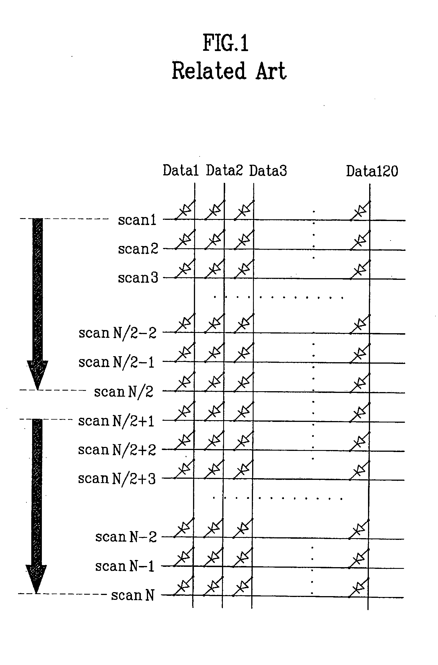
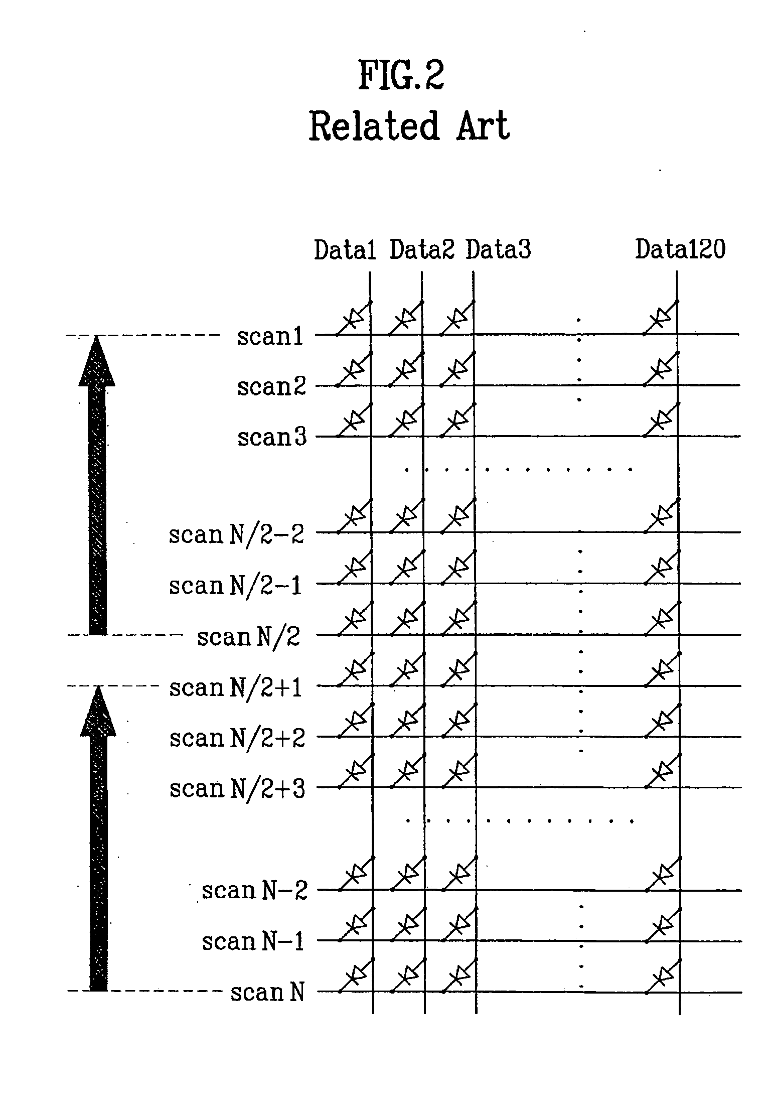
[0037] Each of the display panels shown in FIG. 3 and FIG. 4 has a passive matrix structure of 120 (column lines / data lines)*160 (row lines / scan lines).

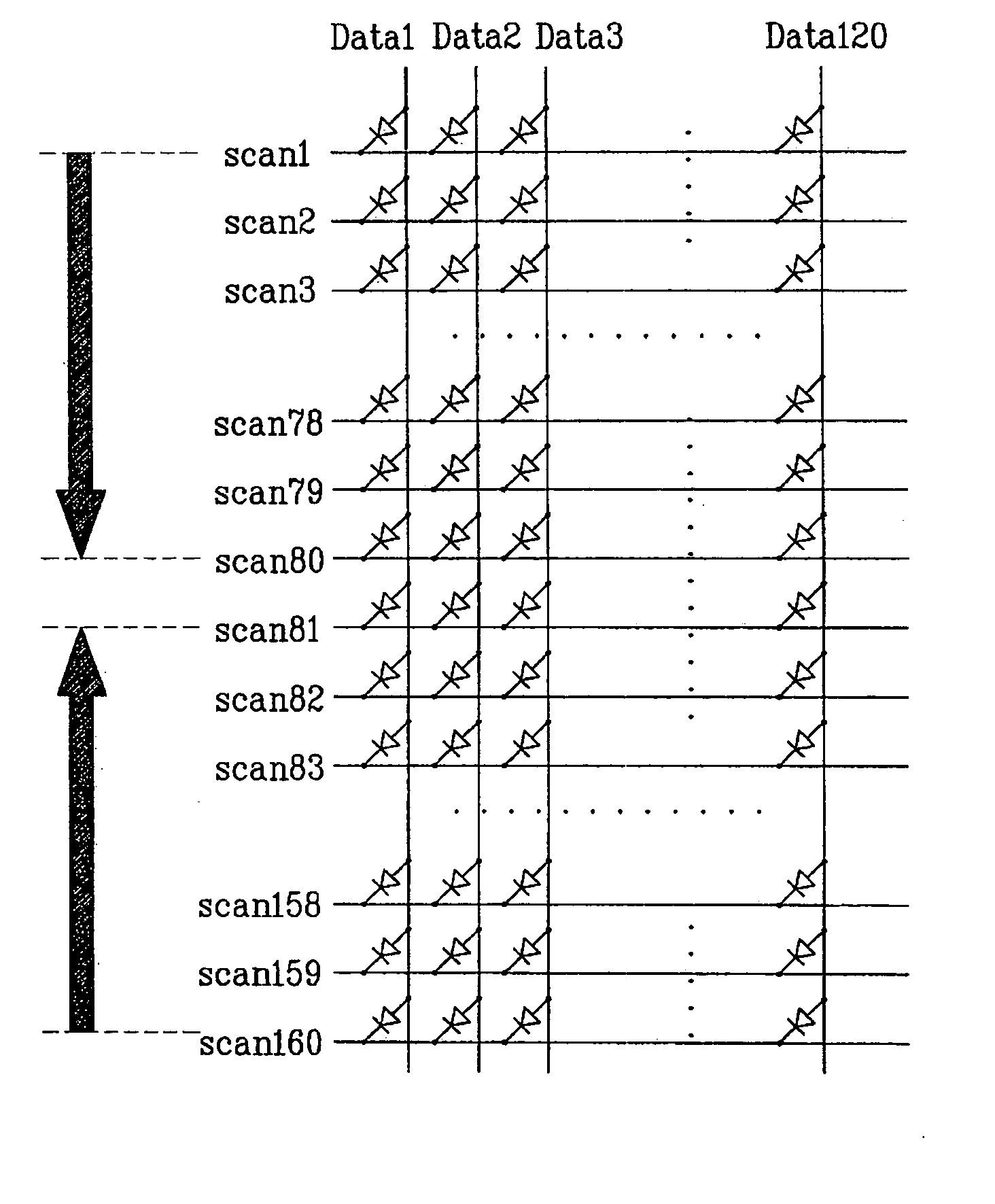
[0038] Each of the display panels of FIG. 3 and FIG. 4 carries out a dual scan on each eighty lines of upper and lower halves of scan lines.

[0039] Referring to FIG. 3, a display panel having one hundred sixty scan lines is divided into an upper half and a lower half.

[0040] Namely, the upper half includes 1st to 80th scan lines and the lower half includes 81st to 160th scan lines.

[0041] A scan line driving se...


PUM


Abstract

Disclosed is a dual scan method of a display panel having M data lines and N scan lines. The present invention includes the steps of dividing the N scan lines into an upper half and a lower half; and applying current to the scan lines of the upper half and the lower half respectively to scan, wherein the scan lines of the upper half and the scan lines of the lower half are sequentially scanned to be symmetrical to each other centering on a central axis of the display panel.

Description

[0001] This application claims the benefit of the Korean Application No. P2002-18659 filed on Apr. 4, 2002, which is hereby incorporated by reference. BACKGROUND OF THE INVENTION [0002] 1. Field of the Invention [0003] The present invention relates to a display panel, and more particularly, to a dual scan method of a display panel having a passive matrix structure. [0004] 2. Discussion of the Related Art [0005] Recently, rapid progress has been made in a flat display panel field. [0006] Specifically, flat display panels including LCD (liquid crystal display) as a leading device appears in the markets to replace CRT (cathode ray tube) having been used most widely in the display field. Lately, the flat display panels including PDP (plasma display panel), VFD (visual fluorescent display), FED (field emission display), LED (light emitting diode), EL (electroluminescence), and the like have achieved great developments. [0007] Such a flat display panel requires a simple manufacturing proc...

Claims


Application Information

Patent Timeline
Patent Type & Authority Applications(United States)
IPC IPC(8): G09G3/20H01L51/50G09G3/30G09G3/32
CPCG09G3/20G09G3/3216G09G2310/0283G09G2310/0221G09G2310/0205G09G3/30
Inventor KIM, HAK SUKIM, JUNG BAENAM, YOUNG HEEKIM, CHANG JIN
Owner LG ELECTRONICS INC
Why Eureka
Try Eureka