Inkjet head printing device

Active Publication Date: 2005-04-07
BROTHER KOGYO KK
View PDF13 Cites 21 Cited by
  • Summary
  • Abstract
  • Description
  • Claims
  • Application Information

AI Technical Summary

Benefits of technology

[0005] It is desired to arrange the nozzles on the inkjet head more densely to increase resolution of the image and/or to improve printing speeds. However, if the density of the nozzles is increased, i.e., the density of the pressure chambers is i

Problems solved by technology

However, if the density of the nozzles is increased, i.e., the density of the pressure chambers is increased, portions of the piezoelectric sheet (active layer) corresponding to neighboring pressure chambers, surrounding a target pressure chamber being applied with pressure, are distorted because of the dense arrangement of the pressure chambers.

Method used


Image

  • Inkjet head printing device
  • Inkjet head printing device
  • Inkjet head printing device

Examples


first embodiment

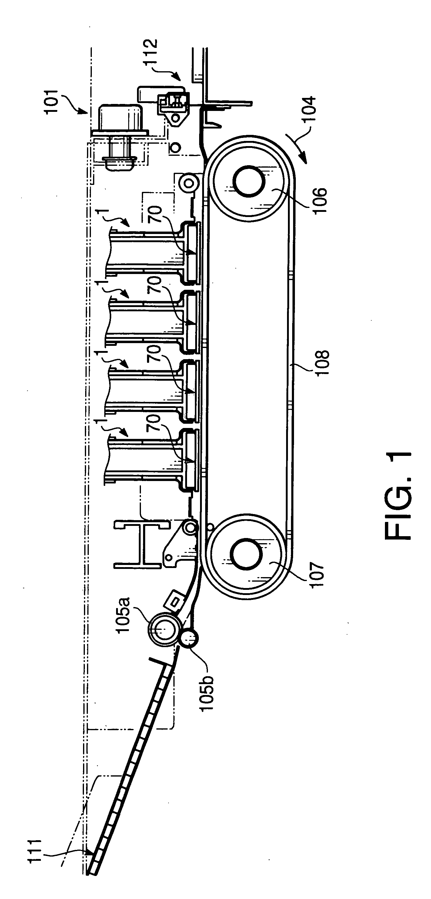
[0065]FIG. 1 schematically shows an inkjet printer 101 according to a first embodiment of the invention. As shown in FIG. 1, the inkjet printer 101 has four inkjet heads 1 for forming color images. In the inkjet printer 101 a sheet feeding unit 111 is located on an upstream side of a sheet feed path, and a sheet ejecting portion 112 is located on a downstream side of the sheet feed path. As described in detail below, the inkjet printer 101 has a control unit 113 which controls operation of the inkjet heads 1.

[0066] As shown in FIG. 1, along the sheet feed path, a pair of sheet feed rollers 105a and 105b is located immediately on the downstream side of the sheet feeding unit 111. By the pair of sheet feed rollers 105a and 105b, the sheet is fed from the sheet feeding unit 111 into the inside of the inkjet printer 101.

[0067] At a midway of the sheet feed path, a carrying belt 108 which is driven by belt rollers 106 and 107 is located. An outer surface of the carrying belt 108 has be...

second embodiment

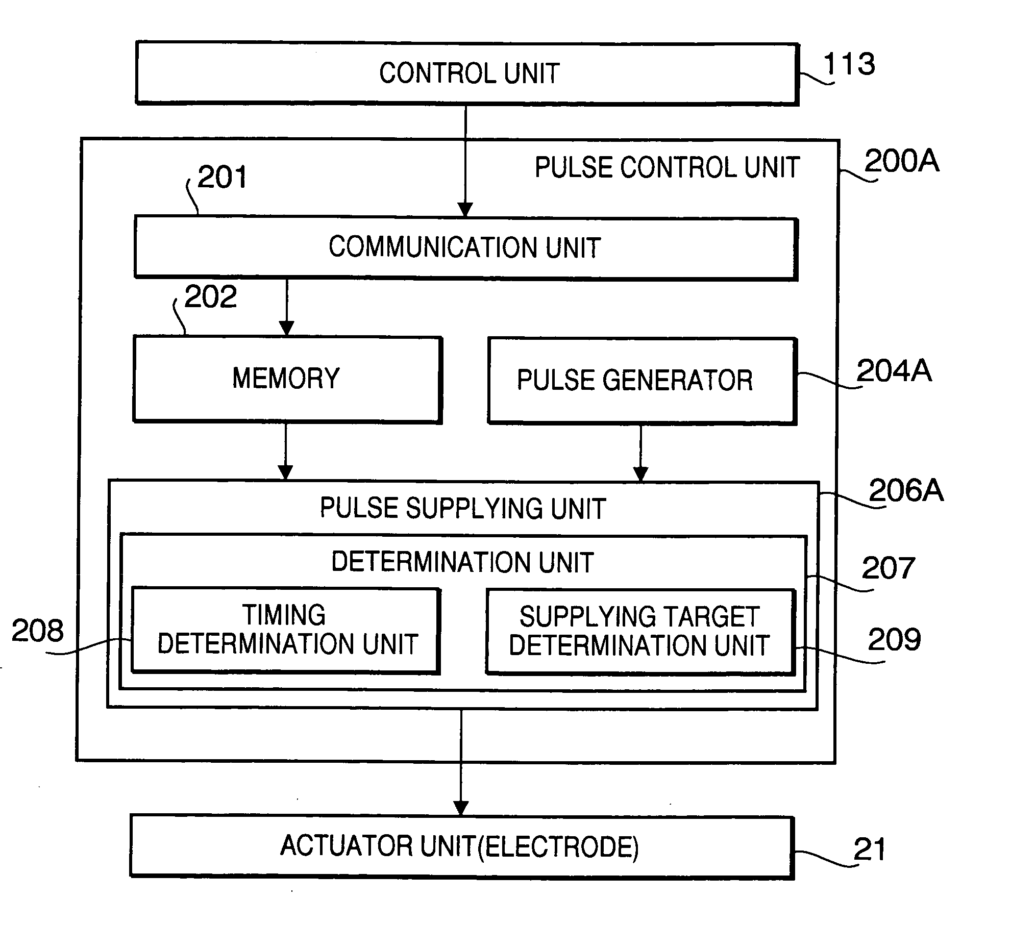
[0150] Next, an inkjet printer according to a second embodiment of the invention will be described. Since in this embodiment only a pulse control unit 200A is different from the pulse control unit 200 of the first embodiment, only the feature of the pulse generator 200A Is described. In FIGS. 15, 16A and 16B, to elements which are substantially the same as those of the first embodiment, the same reference numbers are assigned, and the explanations thereof will not be repeated.

[0151]FIG. 15 is a functional block diagram of the pulse control unit 200A according to the second embodiment. The pulse control unit 200A has the communication unit 201, the memory 202, a pulse generator 204A, and a pulse supplying unit 206A. [01551 The pulse generator 204A generates a plurality of types of ejection pulse patterns having different phases in accordance with a timing number designated by the pulse supplying unit 206A. Further, the pulse generator 204A can generate ejection pulse patterns having...

third embodiment

[0177] Next, an inkjet printer according to a third embodiment of the invention will be described. Since in this embodiment only a pulse control unit 200B is different from the pulse control unit 200 of the first embodiment, only the feature of the pulse generator 200B is described. In FIG. 18, to elements which are substantially the same as those of the first embodiment, the same reference numbers are assigned, and the explanations thereof will not be repeated.

[0178]FIG. 18 is a functional block diagram of the pulse control unit 200B according to the third embodiment. The pulse control unit 200B has the communication unit 201, the memory 202, a pulse generator 204B, and the determination unit 207.

[0179] Hereafter, the pulse control unit 200B that is constituted by the drive IC 80 and the printed circuit board 81 will be explained. Since the functions of the communication unit 201 and the memory 202 are the same as those of the first embodiment, and the function of the determinati...


PUM


Abstract

There is provided an inkjet head printing device, which includes an inkjet head that has an ink flow channel unit including a plurality of nozzles for ejecting ink and a plurality of pressure chambers respectively provided for the plurality of nozzles and has a piezoelectric actuator unit including a plurality of electrodes. The inkjet head further includes a pulse controller that generates a plurality of types of ejection pulse patterns having different phases and drives the plurality of electrodes corresponding to the plurality of nozzles which are to eject the ink using the plurality of types of ejection pulse patterns.

Description

BACKGROUND OF THE INVENTION [0001] The present invention relates to an inkjet head printing device such as an inkjet printer having an inkjet head for ejecting ink to a recording medium. [0002] The inkjet head printing devices have been widely used. Japanese Patent Provisional Publication No. HEI 4-341852 discloses one of conventional inkjet heads employed in the inkjet head printing device. The ink jet head has a fluid channel unit and an actuator unit. The fluid channel unit has a plurality of pressure chambers and a plurality of nozzles provided respectively for the plurality of pressure chambers. Ink introduced into the pressure chambers is ejected from the nozzles by applying pressure to the pressure chambers using the actuator unit. To form an image on a sheet of paper, pressure is selectively applied to the pressure chambers by the actuator unit. [0003] The actuator unit has a laminated structure consisting of a plurality of piezoelectric sheets and a common electrode layer. ...

Claims


Application Information

Patent Timeline
IPC IPC(8): B41J2/045B41J2/055B41J2/14
CPCB41J2/04525B41J2/04573B41J2/04581B41J2/04588B41J2/14209B41J2202/20B41J2002/14225B41J2002/14306B41J2002/14459B41J2202/06B41J2002/14217
Inventor IWAO, NAOTO
Owner BROTHER KOGYO KK
Why Eureka
Try Eureka