Time correlation of ultrafast laser pulses

a laser pulse and time correlation technology, applied in the field of measuring characteristics of ultrafast laser pulses, can solve the problems of becoming, less able to provide signal that gives accurate representation of conventional optical detectors such as photodiode detectors

Active Publication Date: 2005-04-07
COHERENT INC
View PDF6 Cites 35 Cited by
  • Summary
  • Abstract
  • Description
  • Claims
  • Application Information

AI Technical Summary

Benefits of technology

In another aspect of the present invention, an auto-correlation method for laser pulses comprises providing a repetitively pulsed laser resonator delivering a train of pulses having a selectively variable pulse repetition frequency. Each pulse of the pulse train is optically divided into two pulse components. Each pulse component is directed along a different-length path to the detector. The detector provides a response when a pulse component received from one of the paths temporally overlaps a pulse component received from the other pulse component on said detector. The detector response has a magnitude dependent on the degree of temporal overlap of the pulse components. The pulse repetition frequency is selectively varied while maintaining the path lengths fixed. This correspondingly varies the temporal overlap of the pulse components. The magnitude of the response of the detector at a plurality of different degrees of temporal overlap of the pulse components is recorded to provide data from which characteristics of the pulses can be determined.

Problems solved by technology

As the duration of pulses decreases, conventional optical detectors such as photodiode-detectors, become less able to provide a signal that gives an accurate representation of the amplitude and duration of the pulses.

Method used


Image

  • Time correlation of ultrafast laser pulses
  • Time correlation of ultrafast laser pulses
  • Time correlation of ultrafast laser pulses

Examples


Embodiment Construction

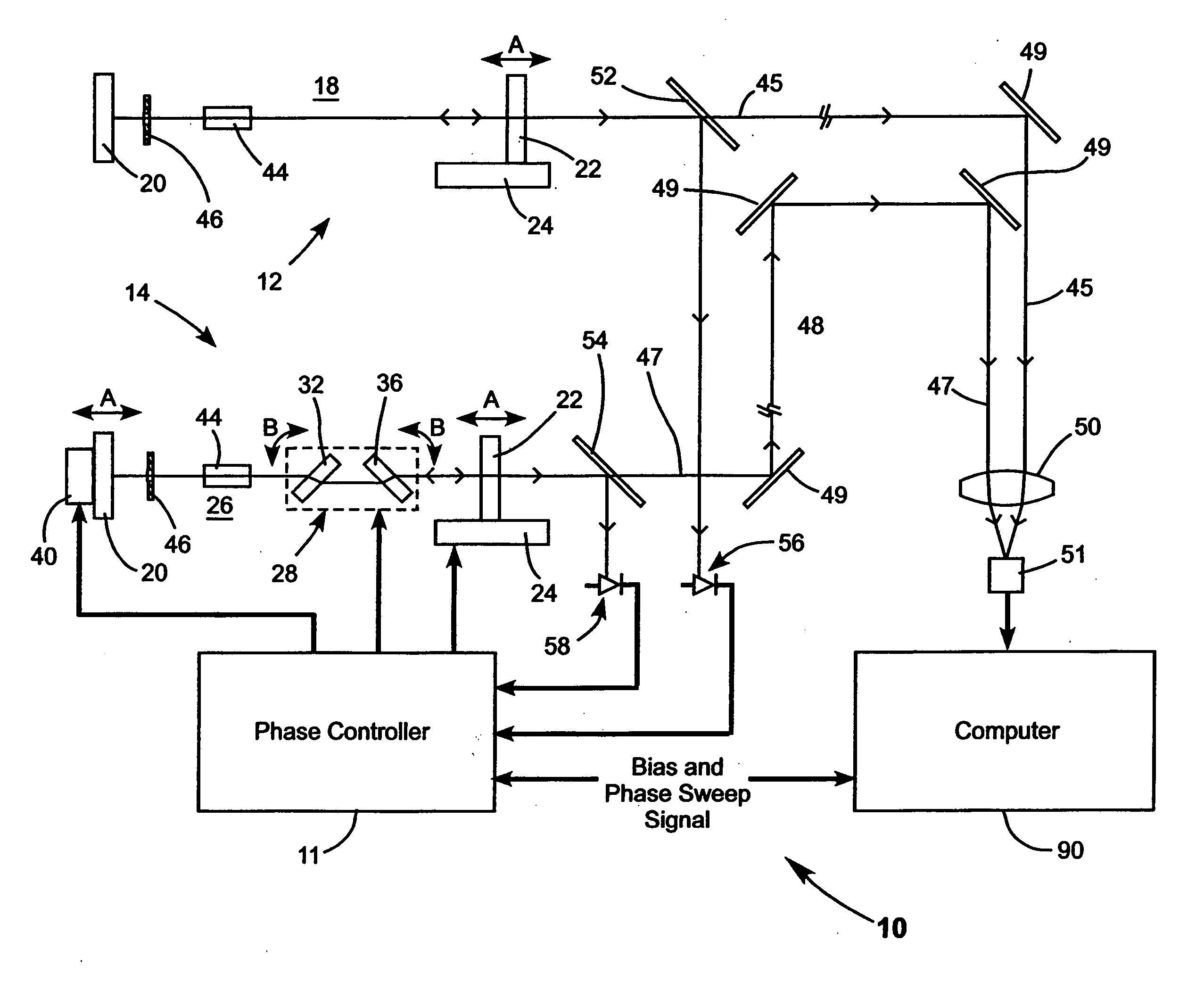
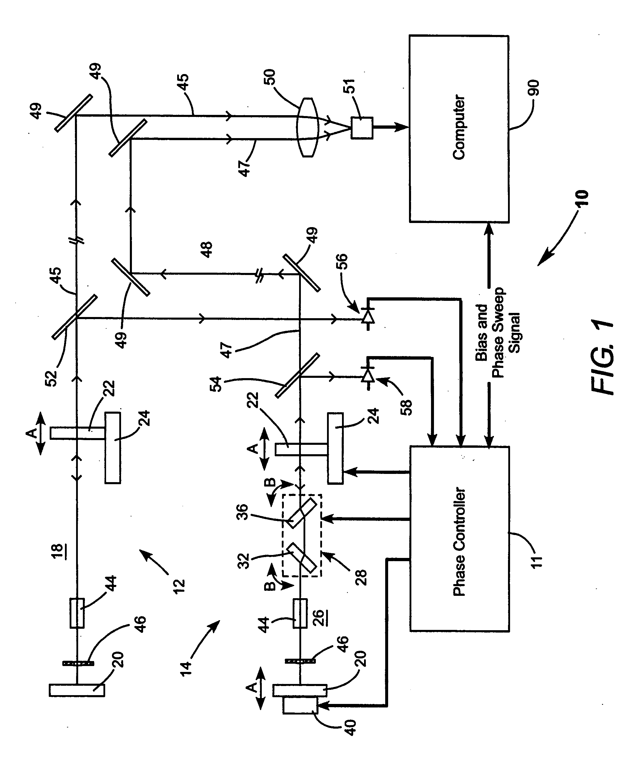
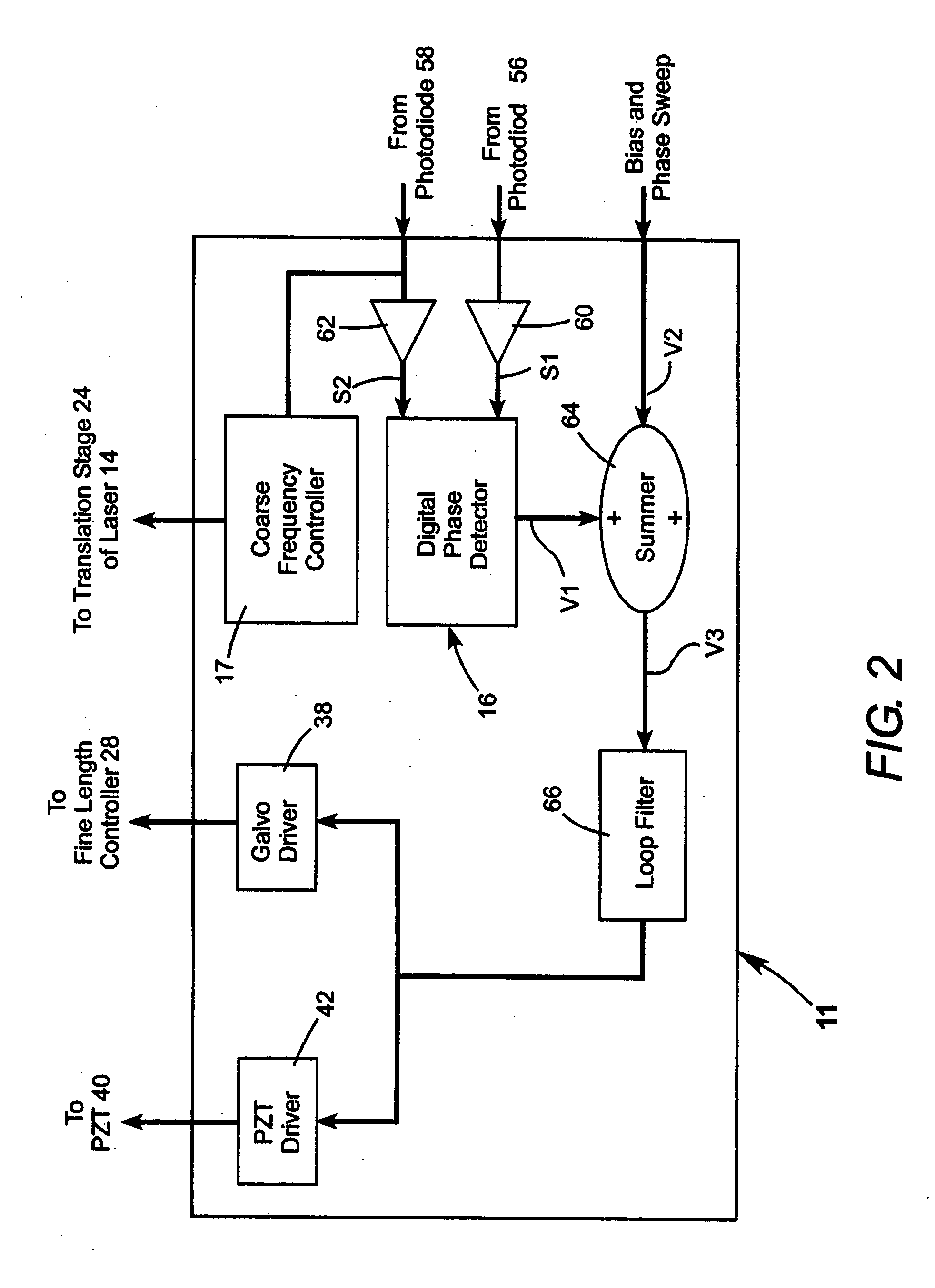
Turning now to the drawings, wherein like features are designated by like reference numerals, FIG. 1 schematically illustrates a preferred apparatus 10 for implementing a cross-correlation method in accordance with the present invention. Apparatus 10 includes two lasers 12 and 14, and a phase (and frequency) controller 11 for synchronizing the output of the lasers. FIG. 2 schematically illustrates the functional layout of a preferred example of a phase controller 11 including a digital phase detector 16. FIG. 3 schematically illustrates electronic circuits and their interconnection in digital phase detector 16. In FIG. 1, the paths of laser pulses in and from the lasers are designated by fine lines, and the direction of propagation of the laser pulses is indicated by open arrows. Connections between electronic circuits and electronic function blocks are indicated in FIG. 1 and FIG. 2 by bold lines, with the direction of signal transfer between the circuits and blocks indicated by s...


PUM


Abstract

Time-correlation methods for determining pulse characteristics from a modelocked ultrafast laser include a cross-correlation method and an auto-correlation method. In the cross-correlation method, pulses from the laser and pulses from another modelocked laser are incident on a two-photon detector that responds when the pulses overlap in time. The lasers are synchronized to the same frequency and the phase difference between pulses from the two lasers is varied to vary the temporal pulse overlap while recording the detector response. Pulse characteristics are determined from recorded data representing the detector response as a function of phase difference. In the auto-correlation method, pulses from one laser are divided into two components. One component follows a fixed delay path before being temporally overlapped at the detector with another component that has not been delayed. The temporal overlap is varied by varying the pulse repetition frequency. Pulse characteristics are determined from recorded data representing the detector response as a function of phase difference.

Description

TECHNICAL FIELD OF THE INVENTION The present invention relates generally to measuring characteristics of ultrafast laser pulses by auto-correlation and cross-correlation of pulses from modelocked ultrafast lasers. The invention relates in particular to auto and cross-correlation methods in which the temporal overlap of pulses or pulse components on a single two-photon detector is varied by varying the phase of pulse trains emitted by two lasers or the frequency of a pulse train emitted by one laser. DISCUSSION OF BACKGROUND ART Ultrafast lasers can deliver very short (ultrafast) pulses at relatively high pulse repetition rates. By way of example pulses may have a duration of 10 picoseconds (Ps) or less at pulse repetition rates between about 75 Megahertz (MHz) and 1 Gigahertz (GHz) or greater. The pulse duration of a passively modelocked laser is determined, inter alia, by the gain-medium in the resonator and the method of passive modelocking. The pulse repetition rate of a passiv...

Claims


Application Information

Patent Timeline
Patent Type & Authority Applications(United States)
IPC IPC(8): G01J11/00
CPCG01J11/00H01S3/10053H01S3/2383H01S3/106H01S3/1394H01S3/105
Inventor PANG, H. YANGAUSTIN, R. RUSSEL
Owner COHERENT INC
Why Eureka
Try Eureka