
Method and apparatus for improving resolution in spectrometers processing output steps from non-ideal signal sources

Inactive Publication Date: 2004-08-12
WARBURTON WILLIAM K
View PDF21 Cites 32 Cited by
  • Summary
  • Abstract
  • Description
  • Claims
  • Application Information

AI Technical Summary

Benefits of technology

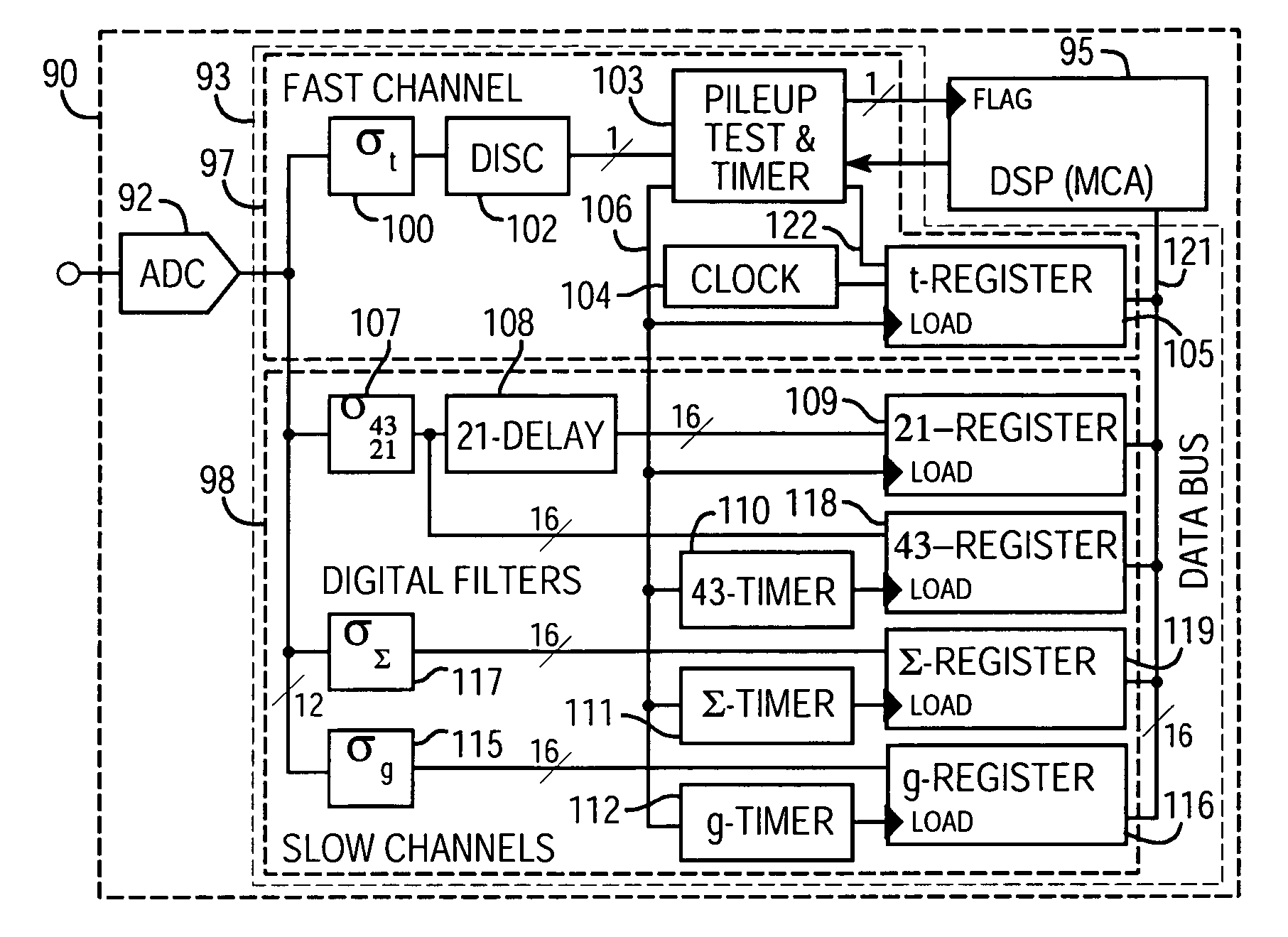
[0039] The TCWFS-filter sum of the cMOS set is the composite signal that contains at least some signal values that are proportional to the pulse's integrated area (or the energy of the event that generated it), provided that the weights are properly valued in relation to the filter functions, the delays, and the time constants in the device. These signal values will be local maxima in the time correlated, weighted filter sum-filter signal and may be captured by peak sensing techniques. They also occur a fixed time interval after the arrival of the step-like pulse in the primary signal and so may also be captured by timing methods. We show how the filter time constants and other elements of the method may be adjusted to increase the duration of the period during which the composite output signal is proportional to the pulse's integrated area, thereby relaxing the timing constraints required in the time capture method. Increasing the duration also increases the range of input pulse risetimes that can be accommodated.
[0046] When using TCWFS-filtering, however, measurement noise is increased by the number N of additional filter samples required to compensate for the N-1P device's multiple terms. For those cases where this increased noise is significant, we also show how N may be reduced by creating a parameterized model of the non-ideal terms; making baseline measurements to determine the parameters; and then using them to correct area (e.g., charge) measurements made using simpler sets of filters which have less noise. In some implementations, these baseline measurements are TCWFS-filter values captured at times when the filters are not processing the step-like signals. In the detector-preamplifier case described in detail, the resultant implementation achieves the low electronic noise levels of conventional trapezoidal filters while also eliminating resolution loss due to both ballistic deficit and high count rates.

Problems solved by technology

When using TCWFS-filtering, however, measurement noise is increased by the number N of additional filter samples required to compensate for the N-1P device's multiple terms.
Therefore, there is an intimate relationship between the weighting coefficients and the filter ranges which, if violated, will introduce inaccuracies.
This is its propagation delay.
A disadvantage of this circuit, compared to FIG. 6A, is that relatively long delays may be required, which may consume excessive gate array resources.
While our preferred implementation is fully digital, the method is not inherently digital per se.
And, as peaking times shorten to obtain higher count rates, the problem will worsen at higher energies.
However, if Q.sub.23 is large, as may be true at high output step rates, then time decay effects in [LQ.sub.23+MB.sub.0].sub.b may still be significant.
Eqn. 38 has two significant problems: 1) increased noise, due to the noise in the single baseline measurement, which is the same size as in the measurement itself and degrades resolution by sqrt(2); and 2) it increases deadtime by at least a factor of two if the two measurements are independent and so separated by at least 2 m+g in time.
However, the time required to pass the multiple secondary signal samples to the digital signal processor, plus the time required to form the weighted signal sum, has been found to set a definite limit on the maximum rate at which events can be processed.

Method used


Image

  • Method and apparatus for improving resolution in spectrometers processing output steps from non-ideal signal sources
  • Method and apparatus for improving resolution in spectrometers processing output steps from non-ideal signal sources
  • Method and apparatus for improving resolution in spectrometers processing output steps from non-ideal signal sources

Examples


Embodiment Construction

to CsI(T1) scintillators

[0231] In the majority of applications described above, the signals were nominally single-pole outputs with perhaps a small second-pole term as an error term in the desired output. The TCWFS-filtering method was originally developed to deal with such signals, and it does so well. However, the method is not restricted to such signals, as we noted earlier and the following example demonstrates. In this case we will look at signals from CsI(T1) scintillators coupled either to photodiodes or photomultiplier tubes. It has been known for some time that CsI(T1) is one of a class of scintillators whose light output decays with at least two different decay time components [SKULSKI-2001], a short component of about 600 ns and a long component of about 4 .mu.s. FIG. 14 shows an output pulse from CsI(T1) when stimulated by a gamma-ray. The shorter and longer components are clearly visible in the output, which is readily described as a two-pole (2-P) device. As a scintill...


PUM


Abstract

A method and apparatus for processing step-like output signals (primary signals) generated by non-ideal, for example, nominally single-pole ("N-1P ") devices. An exemplary method includes creating a set of secondary signals by directing the primary signal along a plurality of signal paths to a signal summation point, summing the secondary signals reaching the signal summation point after propagating along the signal paths to provide a summed signal, performing a filtering or delaying operation in at least one of said signal paths so that the secondary signals reaching said summing point have a defined time correlation with respect to one another, applying a set of weighting coefficients to the secondary signals propagating along said signal paths, and performing a capturing operation after any filtering or delaying operations so as to provide a weighted signal sum value as a measure of the integrated area QgT of the input signal.

Description

[0001] This application is a continuation-in-part of U.S. patent application Ser. No. 10 / 429,170, filed May 1, 2003 (William K. Warburton and Michael Momayezi), which is continuation of U.S. patent application Ser. No. 09 / 643,705, filed Aug. 21, 2000 (William K. Warburton and Michael Momayezi), now U.S. Pat. No. 6,587,814, which claims priority from Provisional U.S. Patent Application No. 60 / 151,020, filed Aug. 27, 1999 (William K. Warburton and Michael Momayezi), all of whose disclosures are incorporated by reference in their entirety for all purposes.[0003] The present invention relates generally to signal processing systems, and more particularly to processing the step-like output signals generated by devices with multiple poles and zeros (including non-ideal, nominally single-pole ("N-1P") devices as a subset) responding to possibly time-varying, pulse-like input signals of finite duration, wherein the goal is to recover the integrated areas of the input signals.[0004] The speci...

Claims


Application Information

Patent Timeline
IPC IPC(8): G06F15/00
CPCG01T1/17
Inventor WARBURTON, WILLIAM K.MOMAYEZI, MICHAEL
Owner WARBURTON WILLIAM K
Learn More