
Image processing device and method

a processing device and image technology, applied in the field of image processing devices and methods, can solve the problems of large storage space, difficult to achieve a low price, and limitation of processing on the computer side, and achieve the effect of effective use of image processing functions, high-speed image processing and size reduction of the device main body, and simple operation

Inactive Publication Date: 2005-04-07
CANON KK
View PDF21 Cites 16 Cited by
  • Summary
  • Abstract
  • Description
  • Claims
  • Application Information

AI Technical Summary

Benefits of technology

[0014] It is another object of the present invention to provide a relatively inexpensive image processing device compatible with various computers and having versatility.
[0016] It is another object of the present invention to provide a device capable of effectively using an image processing function in an external computer to achieve high-speed image processing and size reduction of the device main body, and performing a simple operation such as a copy operation in a stand-alone manner independently of the computer.

Problems solved by technology

However, since such a copying machine having all functions must incorporate various functions of its own, its requirement for a computer with a high throughput and a bulk memory makes it difficult to achieve a low price.
When these units are connected to a computer and used as an input / output equipment, processing on the computer side has a limitation because the units independently perform processing.
Therefore, if the computer is exchanged, all resources are wasted.
However, when the type of the host computer is changed, all resources including the I / O equipment connected to the computer are wasted.
Although an interface for data communication is used for connection in some cases, the data communication control procedures are complex, and a problem of processing rate is posed.
For this reason, connection is difficult for users, and preparation for a plurality of interfaces is costly.

Method used


Image

  • Image processing device and method
  • Image processing device and method
  • Image processing device and method

Examples


Embodiment Construction

[0034] An embodiment of the present invention will be described below with reference to the accompanying drawings.

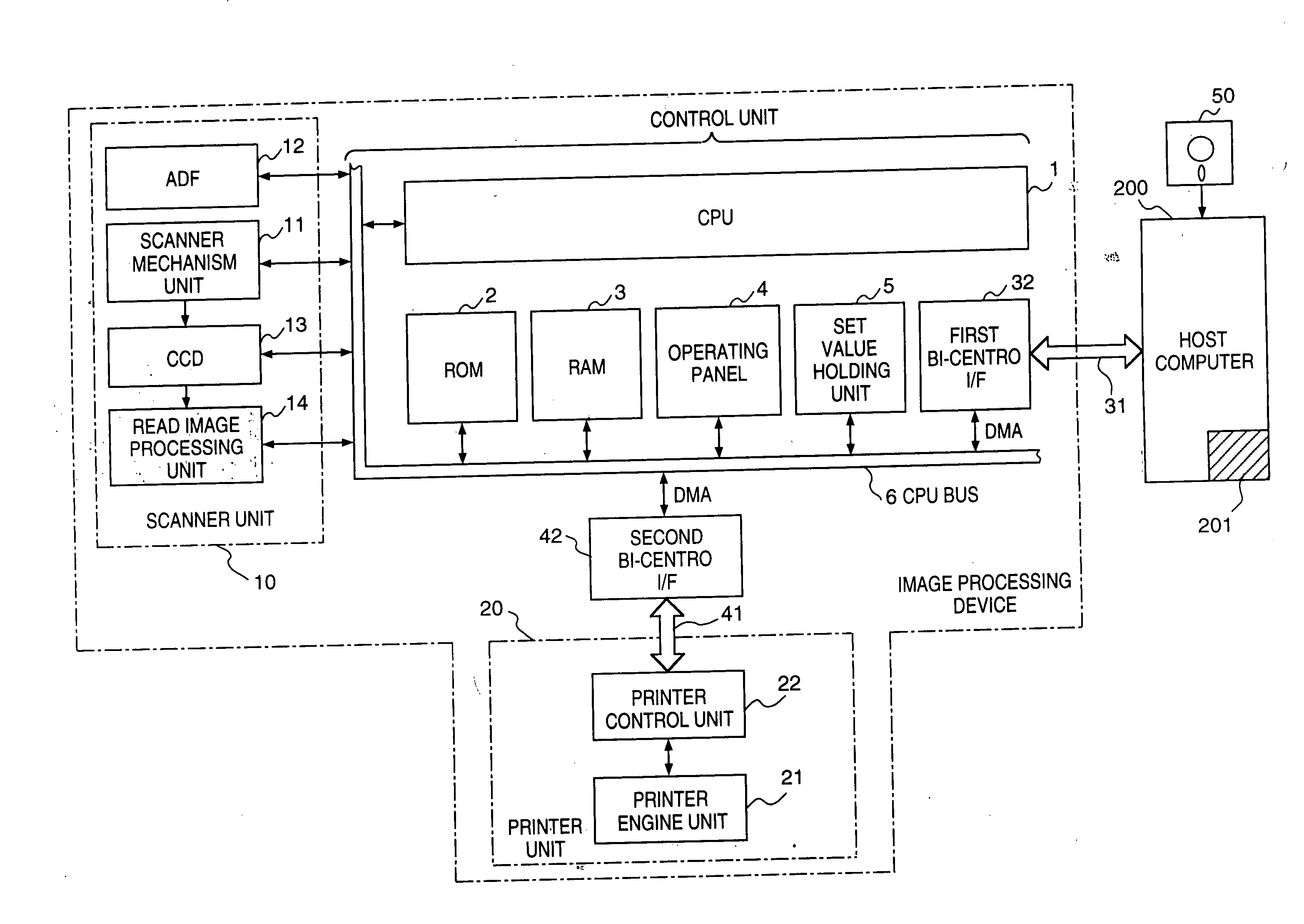
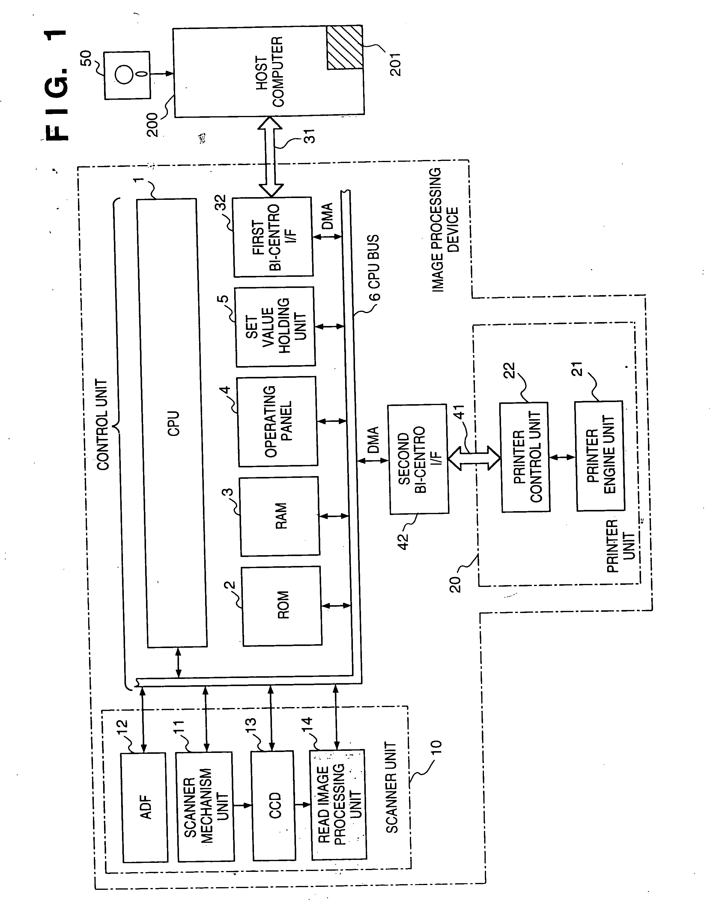
[0035]FIG. 1 is a block diagram showing the arrangement of an image processing device according to an embodiment of the present invention.

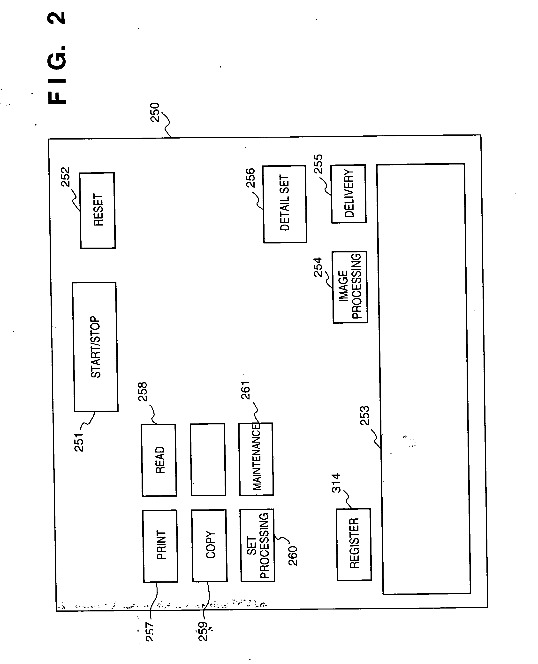
[0036] Referring to FIG. 1, reference numeral 1 denotes a CPU for controlling the entire device; 2, a ROM for storing the control procedures of the CPU 1 and also storing the default values for a scanner and a printer (to be described later), which are used for color image processing; and 3, a RAM for temporarily storing read data from the scanner or print data to the printer. Reference numeral 4 denotes an operating panel unit for inputting a copy operation start instruction or the like, in which a power switch, an on-line / off-line key, a monochrome copy key, a color copy key, a stop key, and the like are arranged. The types of keys are not limited to these. Instead, only a start key is provided, and all the remaining functions may ...


PUM


Abstract

An image processing device connected to a scanner unit for generating a first image signal has a first bidirectional interface for receiving a second image signal from an external computer and a second bidirectional interface for transmitting the first or second image signal to a printer unit. The second bidirectional interface receives a first status signal related to the printer unit and the first bidirectional interface transmits the first status signal and a second status signal related to the scanner unit to the external computer. Therefore, the external computer, which is able to process image data to be printed by the printer unit, can be advised of the status of the printer unit without being directly connected thereto. Therefore, in a first copy mode, the computer can process the image data, while in a second copy mode, the device itself can process the image data.

Description

BACKGROUND OF THE INVENTION [0001] 1. Field of the Invention [0002] The present invention relates to an image processing device and method and, more particularly, to an image processing device and method which allow to perform various image processing by connecting the device to a separate computer. [0003] 2. Description of the Prior Art [0004] Most conventional copying machines in which a scanner unit and a printer unit are integrally arranged operate alone and have all functions necessary for a copy operation. [0005] However, since such a copying machine having all functions must incorporate various functions of its own, its requirement for a computer with a high throughput and a bulk memory makes it difficult to achieve a low price. [0006] When these units are connected to a computer and used as an input / output equipment, processing on the computer side has a limitation because the units independently perform processing. When only the scanner unit or only the printer unit is to b...

Claims


Application Information

Patent Timeline
IPC IPC(8): H04N1/00H04N1/32
CPCH04N1/00127H04N1/00204H04N2201/0049H04N2201/0046H04N1/00278
Inventor NOBUTA, HIROSHINAGANE, HIROMICHISAKAMOTO, MASAHIROMATSUMOTO, KOICHI
Owner CANON KK
Learn More