Monitor for an optical fibre and multi-guide optical fibre circuits and methods of making them

a technology of optical fiber and optical fiber circuit, which is applied in the direction of transmission, photometry, structural/machine measurement, etc., can solve the problems of unsatisfactory methods, high loss and potential mechanical reliability problems, and enhance the possibility of corrupting signals, so as to achieve high yield and better control of exposed length

Inactive Publication Date: 2005-04-07
BADCOCK RODNEY +2
View PDF4 Cites 245 Cited by
  • Summary
  • Abstract
  • Description
  • Claims
  • Application Information

AI Technical Summary

Benefits of technology

[0010] Although all methods are feasible for the invention discussed here, the preferred approach is to grind and polish one side of the fibre which has advantages of providing a flat exposed side to a

Problems solved by technology

These qualities, which make the fibre an ideal transmission medium make the optical signal difficult to access from outside the fibre without either interrupting the light path or bending the fibre to allow light to escape, in both cases considerably enhancing the possibility of corrupting the signal.
Both methods introduce high loss and potential mechanical reliability problems.
However, this method is unsatisfactory since

Method used


Image

  • Monitor for an optical fibre and multi-guide optical fibre circuits and methods of making them
  • Monitor for an optical fibre and multi-guide optical fibre circuits and methods of making them
  • Monitor for an optical fibre and multi-guide optical fibre circuits and methods of making them

Examples


Embodiment Construction

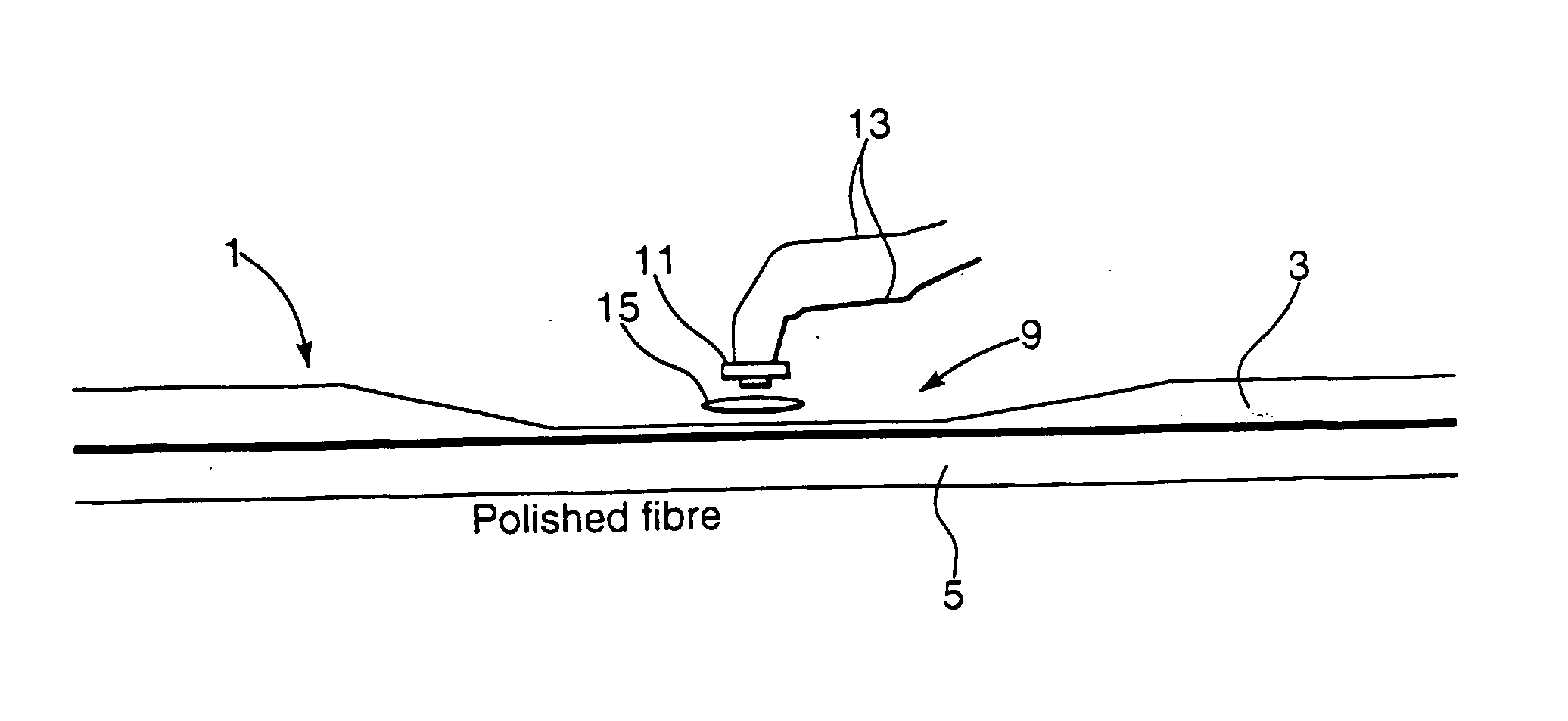
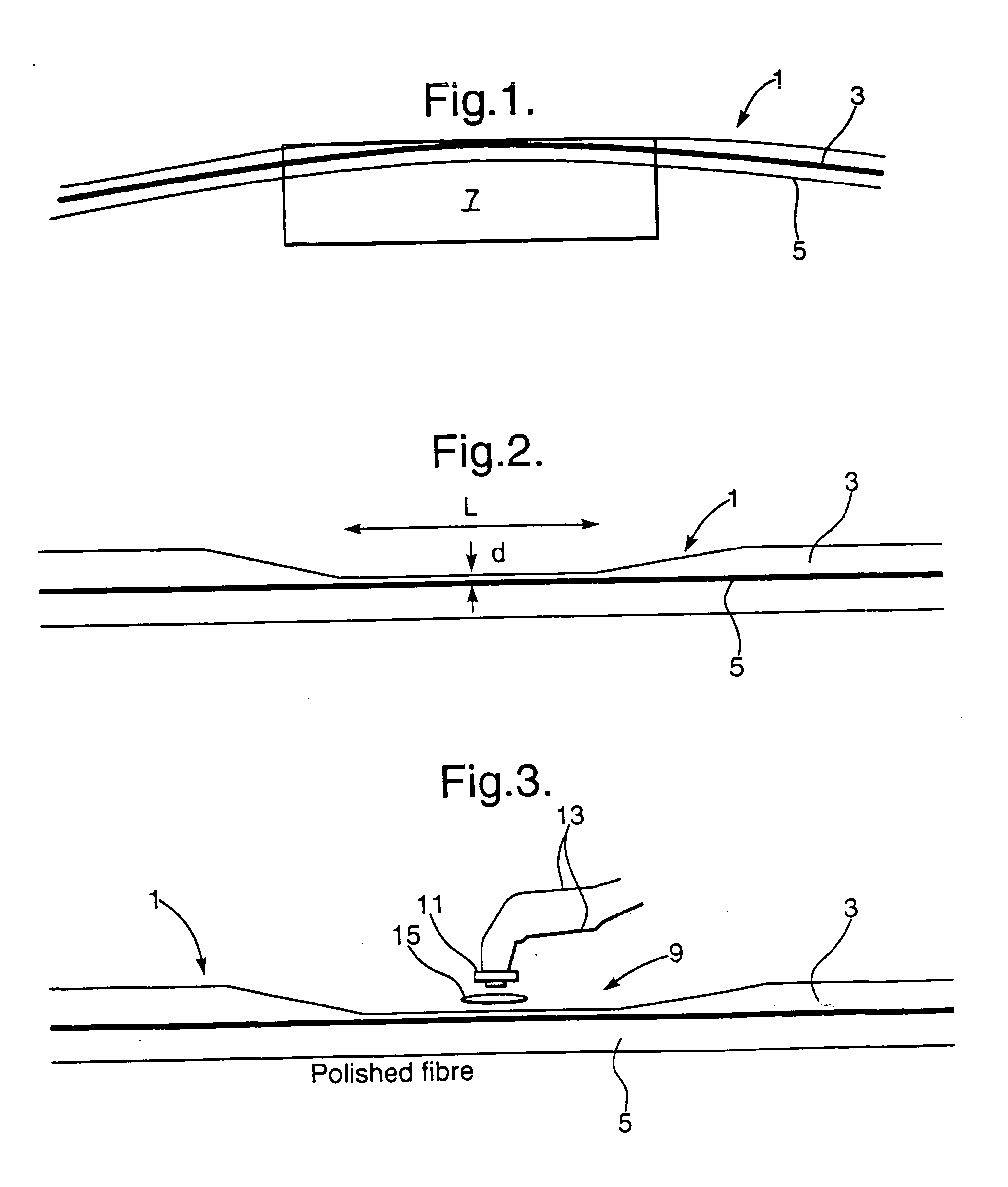
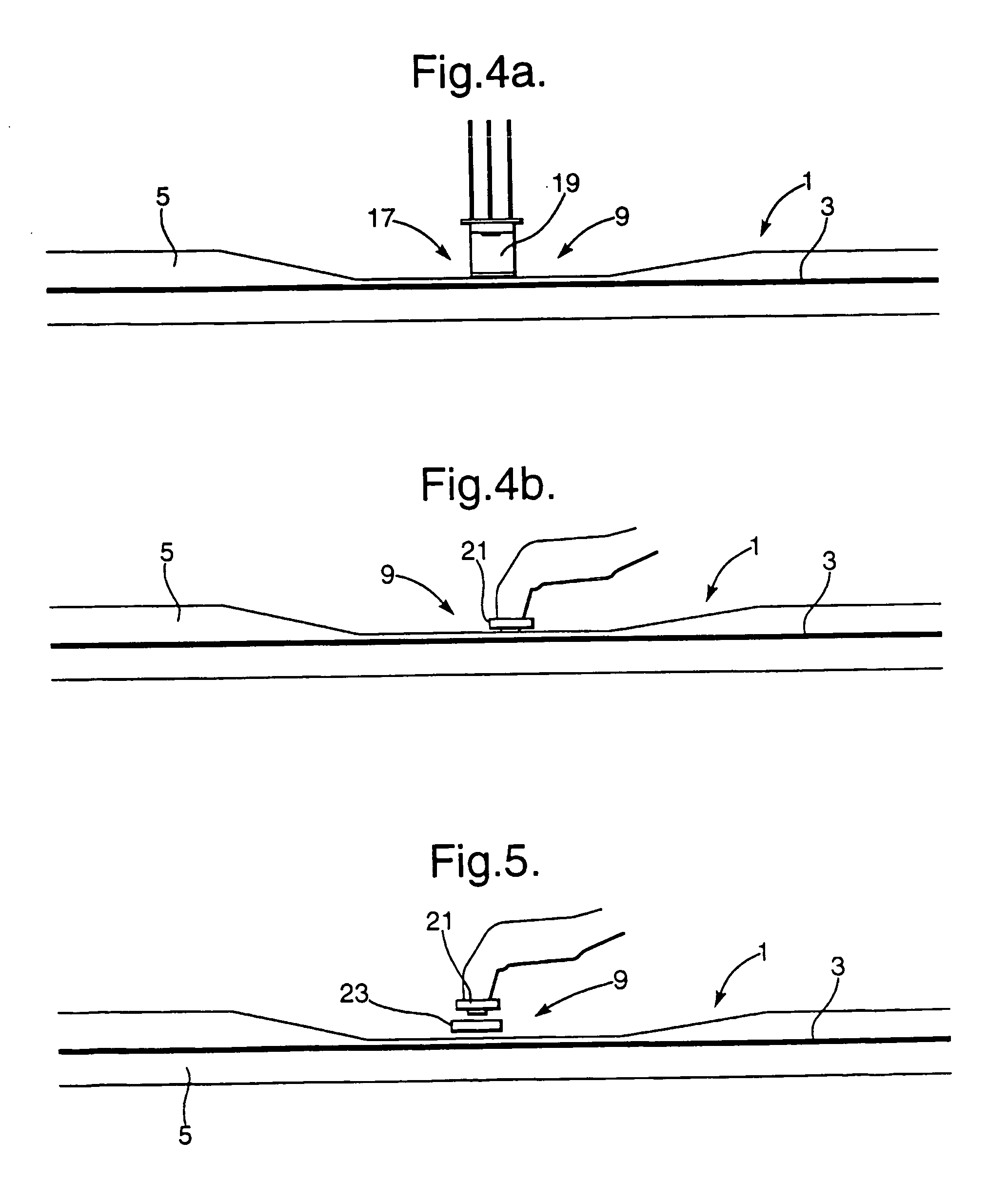
[0077] Referring firstly to FIG. 3, a first embodiment of the invention is shown. The figure shows an optical fibre 1 having a cladding 3 and core 5 with an access region 9 in which the cladding 3 is reduced by the method discussed above in relation to FIG. 2. An optical detector 11 provided with electronic output leads 13 is positioned adjacent to the optical fibre 1 in the region 9 so that it detects the evanescent field and converts this into an electrical signal on the leads 13. A lens 15 may be provided between the fibre 1 and the photo detector 11 if desired.

[0078] In practice, an holding mechanism (not shown) is used for holding the optical fibre with the exposed face vertical, such as a V-groove etched or machined into a suitable mounting material to hold the fibre firmly and allow it to be fixed permanently. The photo detector 11 is likewise mounted in the mounting material with its active area in close proximity to the exposed face of the access region 9 so as to mechanic...


PUM


Abstract

The invention relates to a monitor for monitoring at least one optical signal parameter in an opticl fibre having an access region of reduced cladding sufficient to allow access to the evanescent field. The monitor includes an optical element mountable adjacent to the access region of an optical fibre which optical element is capable of obtaining access to the evanescent field to enable use of the data therein to derive the at least one optical signal parameter.

Description

FIELD OF THE INVENTION [0001] This invention relates to a monitor for an optical fibre for monitoring properties thereof. BACKGROUND OF THE INVENTION [0002] The propagating wave in an optical fibre is contained within the Silica core and is guided along the fibre with very little loss. The primary requirement from the fibre is to transmit the light within to the required destination, with low loss and no interference from the outside environment, which may corrupt the information carried by the light. These qualities, which make the fibre an ideal transmission medium make the optical signal difficult to access from outside the fibre without either interrupting the light path or bending the fibre to allow light to escape, in both cases considerably enhancing the possibility of corrupting the signal. Both methods introduce high loss and potential mechanical reliability problems. [0003] In many fibre applications it is desirable to establish whether there is light in the fibre and moni...

Claims


Application Information

Patent Timeline
IPC IPC(8): G01J1/42G01J9/00G01M11/00G02B6/26G02B6/28G02B6/42H04B10/00H04B10/02H04B10/08
CPCG01J1/4257G01J9/00G01M11/35H04B10/00G02B6/2852G02B6/4249G02B6/266G02B6/4213G02B6/4215G02B6/4286G02B6/429
Inventor BADCOCK, RODNEYGILES, IAN PETERPARWAZ, SHAFIG
Owner BADCOCK RODNEY
Why Eureka
Try Eureka