Fuel pump for a fuel tank

a fuel pump and fuel tank technology, applied in the direction of liquid fuel engines, piston pumps, positive displacement liquid engines, etc., can solve the problems of large axial overall height of the fuel pump and high cost-intensive outlay in the fuel tank, and achieve the effect of avoiding turbulence in the inlet duct, uniform acceleration of the flow, and simple way

Inactive Publication Date: 2005-04-07
CONTINENTAL AUTOMOTIVE GMBH
View PDF3 Cites 7 Cited by
  • Summary
  • Abstract
  • Description
  • Claims
  • Application Information

AI Technical Summary

Benefits of technology

[0007] According to another advantageous development of the invention, a different pressure build-up of the two conveying chambers of the impeller arranged nearest to the inlet duct can be evened out in a simple way when a connection in the partition connects all the conveying chambers of the two impellers to one another.
[0008] According to another advantageous development of the invention, a uniform acceleration of the flows in the conveying chambers between the inlet duct and the outlet duct can be achieved in a simple way when the partition has two connections and when in each case the radially inner of the conveying chambers of one impeller is connected to the radially outer conveying chamber of the other impeller.
[0009] According to another advantageous development of the invention, the fuel pump according to the invention can be manufactured in an especially simple way when in each case the radially outer conveying chambers and the radially inner conveying chambers are connected to one another. By virtue of this configuration, the connections can penetrate through the partition along a straight path.
[0010] According to another advantageous development of the invention, turbulences in the inlet duct can be avoided in a simple way when the inlet duct has a web for dividing the conveying chambers.
[0011] According to another advantageous development of the invention, turbulences in the outlet duct can be avoided in a simple way when the outlet duct has a web for dividing the conveying chambers.
[0012] According to another advantageous development of the invention, the supply of fuel to a suction jet pump requires an especially low outlay in structural terms when the impeller arranged at the inlet duct has a further conveying chamber arranged concentrically to the other conveying chambers and separated from these and when the further conveying chamber has its own outlet.

Problems solved by technology

This results in a very large axial overall height of the fuel pump.
This, however, leads to a highly cost-intensive outlay in the fuel tank.

Method used


Image

  • Fuel pump for a fuel tank
  • Fuel pump for a fuel tank
  • Fuel pump for a fuel tank

Examples


Embodiment Construction

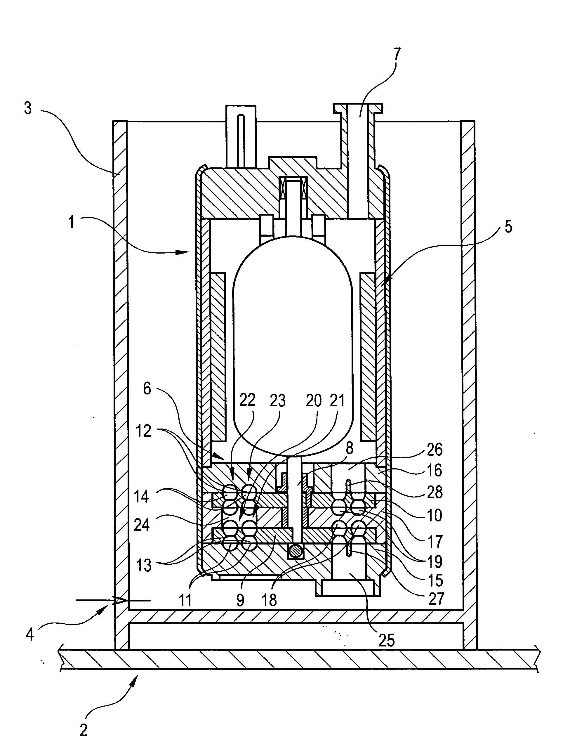
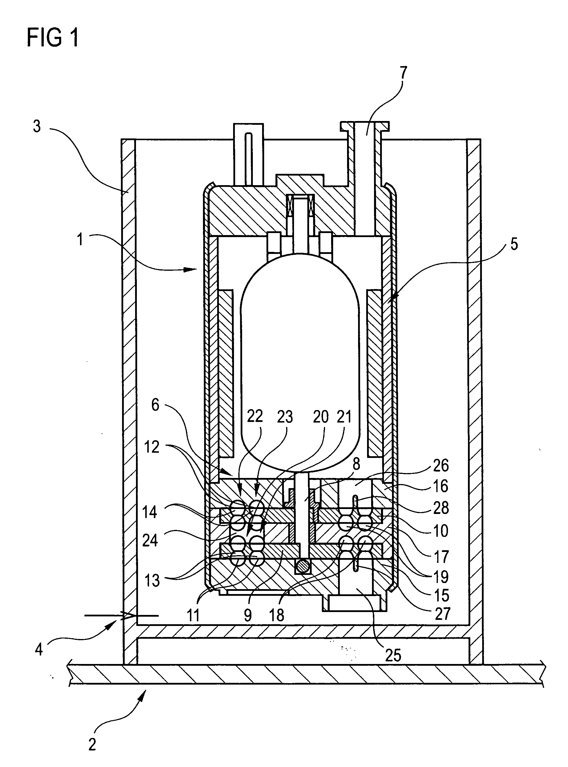
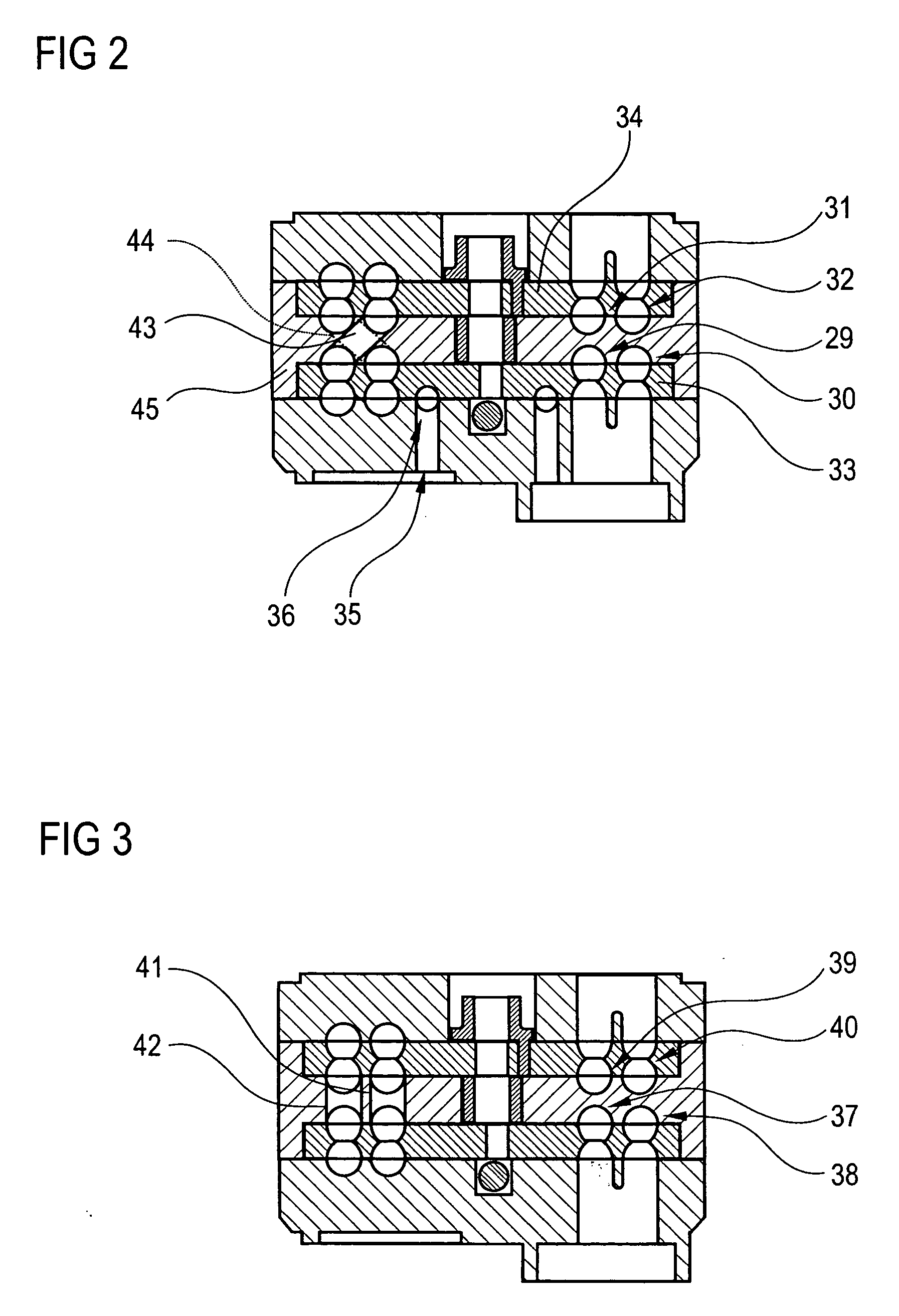
[0017]FIG. 1 shows a longitudinal section through a conveying unit 1 for the conveyance of fuel out of a fuel tank 2 to an internal combustion engine, not illustrated, of a motor vehicle. The conveying unit 1 is arranged in a baffle 3 prestressed against a bottom region of the fuel tank 2. The baffle 3 is filled with fuel from the fuel tank 2 via a suction jet pump 4. The conveying unit 1 has a fuel pump 6 driven by an electric motor 5 and a connection piece 7 for a fuel line leading to the internal combustion engine and the suction jet pump 4. The fuel pump 6 has two impellers 9, 10 arranged fixedly in terms of rotation on a shaft 8 of the electric motor 5, in each case with two rings, one surrounding the other concentrically, of guide blades 11, 12 which delimit blade chambers 13, 14. Blade chambers 13, 14, located opposite one another, of each of the impellers 9, 10 are connected to one another. The flow consequently passes through the impellers 9, 10 axially. The impellers 9, 10...


PUM


Abstract

In a fuel pump (6) designed as a side channel pump, in each case two conveying chambers (20-23) one surrounding the other concentrically are arranged on two impellers (9, 10). The conveying chambers (20, 21) of one impeller (9) are connected to an inlet duct (25), while the conveying chambers (22, 23) of the other impeller (10) are connected to an outlet duct (26). A connection (24) of the conveying chambers (20-23) is arranged in a partition (17) keeping the impellers (9, 10) at a distance from one another. As a result, the fuel pump (6) has an especially high volume flow, along with a very high conveying pressure.

Description

BACKGROUND OF THE INVENTION [0001] The invention relates to a fuel pump for a fuel tank of a motor vehicle, with an impeller arranged rotatably in a casing, with at least two rings, arranged in the two end faces of the impeller and one surrounding the other concentrically, of guide blades which delimit blade chambers, blade chambers located opposite one another being connected to one another, and with part-annular channels, arranged in the casing and located opposite the guide blades, for the formation of conveying chambers, one surrounding the other concentrically, for the conveyance of fuel from an inlet duct to an outlet duct. [0002] Such fuel pumps are often used for the conveyance of fuel from fuel tanks to internal combustion engines of present-day motor vehicles and are known from practice. In the known fuel pump, one of the conveying chambers of the known fuel pump leads to the outlet duct and the other of the conveying chambers leads to an outlet, via which, for example, a ...

Claims


Application Information

Patent Timeline
Patent Type & Authority Applications(United States)
IPC IPC(8): F04D5/00
CPCF04D5/005F02M37/04F02M37/10F04D5/00
Inventor DEICHMANN, JOHANNESGEISSEL, EBERHARDJAEGER, BERND
Owner CONTINENTAL AUTOMOTIVE GMBH
Why Eureka
Try Eureka