A rapid tool drop device for a lathe

A technology of falling knife and lathe, which is applied in the field of cutting processing, can solve the problems of difficult accurate calculation of shear force, large vibration, and inability to maintain the spring end face, etc., to avoid differences caused by samples, avoid material waste, and save test costs.

Active Publication Date: 2019-01-01
DALIAN UNIV OF TECH
View PDF6 Cites 0 Cited by
  • Summary
  • Abstract
  • Description
  • Claims
  • Application Information

AI Technical Summary

Problems solved by technology

The hammer-type rapid tool drop device vibrates greatly when the hand hammer is struck, which affects the cutting of the tool and has an impact on the accuracy of the machine tool; the gunshot type rapid tool drop device has a high operating risk factor; the explosive type rapid tool drop device has uneven acceleration. The initial acceleration value is smaller than the value that can be achieved later, and the operation is complicated. It is difficult to accurately calculate the amount of explosive charge and the shear force required to break the pin, and the operation is unsafe and noisy.
All of the above rapid tool drop devices need to cut the shear pins. At present, there are some patents that avoid damage to the shear pins through structural design. The form of tool drop is that the tool rotates, but the rotation axis of the tool is lower than the center level of turning, which makes the tool The movement track (arc) of the point-dropping tool intersects the outer circle of the workpiece, causing the tool tip to squeeze the workpiece, which has an adverse effect on the chip root and the tool tip, and if the spring compression is used as the power, the end face of the spring cannot be kept tight during the tool rotation. Sticking to the surface of the tool, the spring cannot always maintain good contact with the tool rod, resulting in an error in the acceleration of the tool drop

Method used


Image

  • A rapid tool drop device for a lathe
  • A rapid tool drop device for a lathe
  • A rapid tool drop device for a lathe

Examples


Embodiment Construction

[0031] The specific implementation manners of the present invention will be further described below in conjunction with the accompanying drawings and technical solutions.

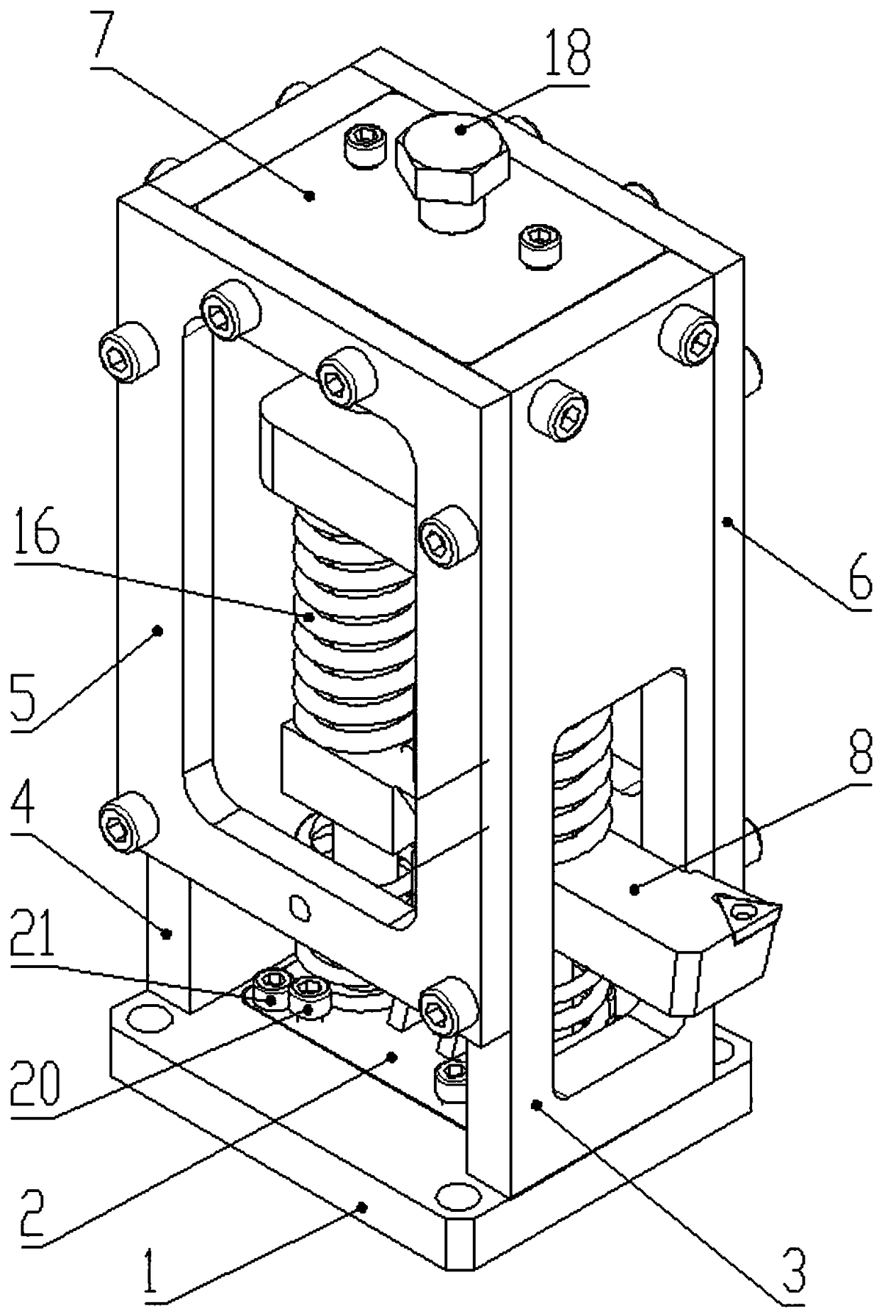
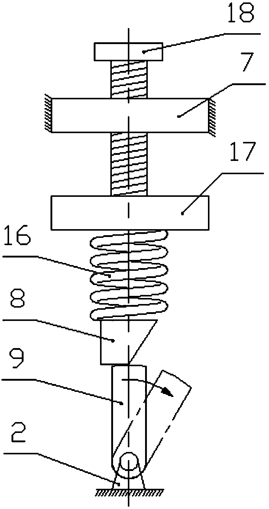
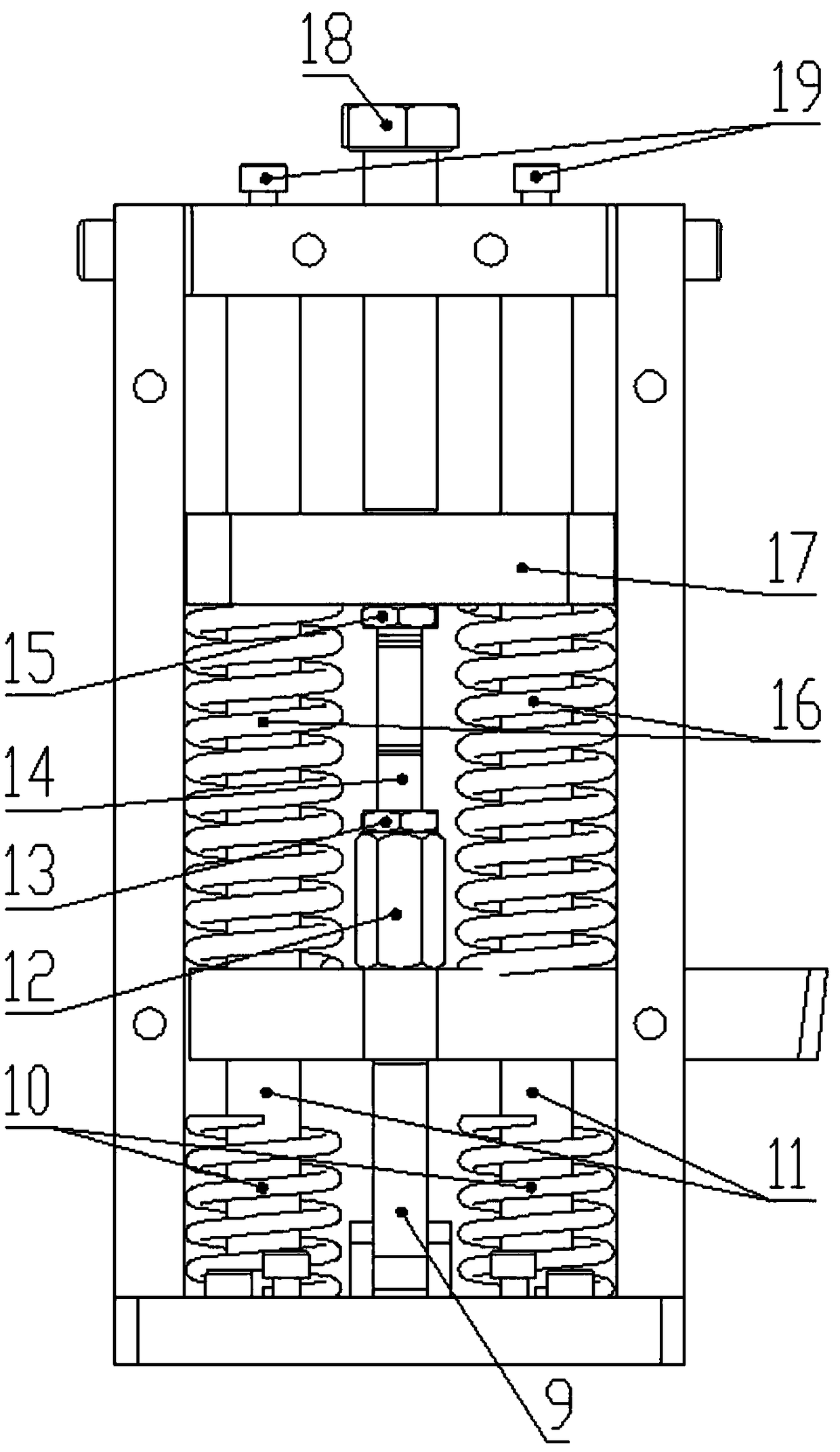
[0032] Such as Figure 1 to Figure 9 Shown, the present invention is a kind of fast tool drop device for lathe, base 1, bottom plate 2, front side plate 3, rear side plate 4, right side plate side 5, left side plate 6, top fixed plate 7, knife bar 8, Cam lever 9, buffer spring 10, cylindrical guide rail 11, adjustment nut 12, first lock nut 13, stud stud 14, second lock nut 15, pressure spring 16, pressure plate 17, compression bolt 18, guide rail fixing Screw 19, height adjustment screw 20, fastening screw 21, bearing pin 22; the device of the present invention is fixed on the lathe through the base 1, the present invention does not limit its fixing method and fixing position, those skilled in the art can choose according to the actual situation , For example, it can be installed on the middle carriage of...


PUM


Abstract

The invention belongs to the technical field of cutting and processing, and provides a rapid tool drop device for a lathe, which includes a base, a bottom plate, a front side plate, a rear side plate, a right plate side, a left side plate, a top fixing plate, a knife rod, a cam rod, a buffer It consists of a spring, a cylindrical guide rail, an adjusting nut, a lock nut, a double-ended stud, a lock nut, a pressure spring, a pressure plate, a pressure bolt and a pin. The cam rod supports the knife rod before the knife falls. When the knife needs to be dropped, the external force makes the cam rod rotate. When the cam rod turns over a certain position, the knife rod loses its supporting force instantly. The tool drops with great acceleration, leaving the cutting area in a short time and freezing the root of the chip. The invention has the advantages of simple structure, low manufacturing cost, safe and convenient operation, small impact, reusable use, short reset time, no interference between the tip of the knife and the workpiece when dropping the knife, no damage to the chip root, and rapid and effective knife dropping.

Description

technical field [0001] The invention belongs to the technical field of cutting processing, and relates to a rapid tool drop device for a lathe. Background technique [0002] In order to study the cutting mechanism of the metal cutting process, various rapid tool drop mechanisms are widely used at home and abroad. Through the sudden tool drop during the cutting process, the deformation zone and chip root samples under the cutting conditions are obtained, and then different methods are used to analyze the cutting mechanism. It observes and establishes various physical models of chip formation to reveal the metal cutting mechanism and achieve the purpose of describing or predicting the cutting process. In order to make the chip root sample closer to the state during cutting, when designing the rapid tool drop device, the tool drop acceleration must be large enough, the separation time between the tool and the workpiece should be as short as possible, and the trajectory of the t...

Claims


Application Information

Patent Timeline
Patent Type & Authority Patents(China)
IPC IPC(8): B23B25/00
CPCB23B25/00B23B29/18B23B27/08B23Q17/2233B23B25/06
Inventor 段春争刘玉敏孙伟孙玉文张方圆鞠康
Owner DALIAN UNIV OF TECH
Why Eureka
Try Eureka