Multifunctional modular system for energy transformation

An energy conversion and modularization technology, applied in the field of multifunctional modular systems for energy conversion, can solve problems such as unrealistic, infeasible promotion and application, and achieve the effect of low manufacturing

Inactive Publication Date: 2007-11-14
尤泰姆公司
View PDF0 Cites 0 Cited by
  • Summary
  • Abstract
  • Description
  • Claims
  • Application Information

AI Technical Summary

Problems solved by technology

However, trains operating by electromagnetic levitation currently ha...

Method used


Image

  • Multifunctional modular system for energy transformation
  • Multifunctional modular system for energy transformation

Examples


Embodiment Construction

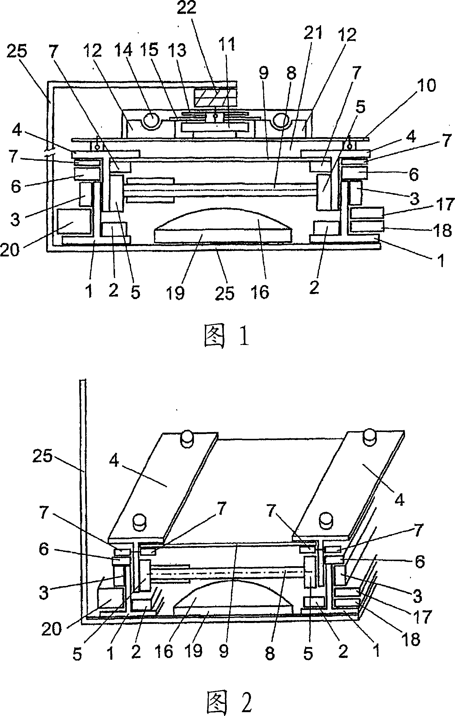
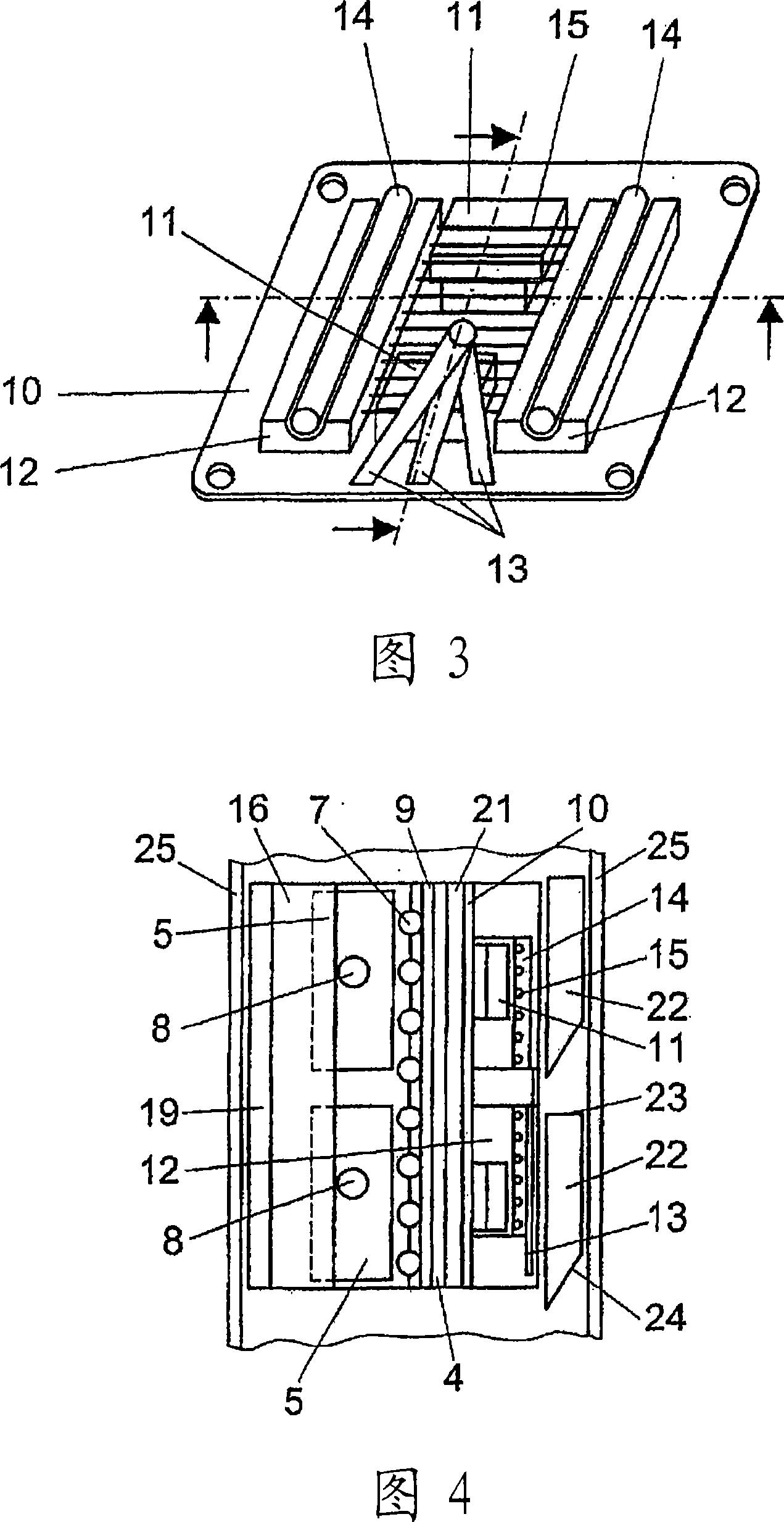
[0030]All these figures show that the invention is characterized by comprising two supports 1 having an inverted T-shaped cross-section, each of these supports being made of a very strong, lightweight, easy-to-handle, inexpensive and Durable non-ferromagnetic material along with synthetic resin allows for several adjustments, finishing and simple replacement when required.

[0031] In the lower part of each of the above-mentioned inverted T-shaped supports 1 is accommodated and installed a magnet 2 covered with resin to provide punctuality and weather resistance and adaptability to the system; the size of the magnet 2 is specified longitudinally and axially , ie thickness, height, and magnetic orientation to provide in particular a force vector assembly with specified values ​​and angles to form the rest of the assembly of the magnetic generator with constant force and stable balance.

[0032] At the top of the vertical wall of each inverted T-shaped support 1, near the vertic...


PUM


Abstract

In accordance with the present invention one device for locating ferrous object(s) that are visually obscured by a non-magnetic surface material and for temporarily holding a mostly ferrous fastener in the correct position to be affixed until firmly started.

Description

technical field [0001] As stated in the title of the invention, the object of the present invention is a system consisting of a set of modules that together define a multifunctional modular energy conversion system, preferably for rail transport. Background technique [0002] The prior art relevant to this invention includes several previous trains operating by electromagnetic levitation, since this technology offers considerable advantages for application in this type of transportation, especially when the aim is to achieve at higher speeds. However, trains operating by electromagnetic levitation currently have disadvantages that make their widespread use unfeasible and unrealistic. Contents of the invention [0003] Historically, the development of rail transport technology has revolved around two main options. One is considered a traditional high-speed train; the other is a train that levitates and moves based on electromagnetic energy. [0004] Even though there has...

Claims


Application Information

Patent Timeline
IPC IPC(8): B61B13/08B60L13/04
CPCY02T30/40B60L2200/26Y02T30/00
Inventor 马卡里奥·巴克罗·莫查莱斯
Owner 尤泰姆公司
Why Eureka
Try Eureka