
Improved engine control

A technology of control unit and propulsion power, which is applied in the direction of propulsion engine, motor-driven engine, motor vehicle, etc. It can solve the problems of changing operating conditions, time-consuming and expensive control unit, etc., and achieve the effect of consistent acceleration performance

Pending Publication Date: 2021-05-25
CPAC SYST
View PDF12 Cites 0 Cited by
  • Summary
  • Abstract
  • Description
  • Claims
  • Application Information

AI Technical Summary

Problems solved by technology

This consistency may be difficult to achieve when using a speed control function optimized for a single operating scenario, as operating conditions may change
[0007] Basing the control of the propulsion unit on signals internal to the propulsion unit can be a problem because it can be expensive to connect these internal signals to a control unit external to the propulsion unit.
Also, this control system then needs to be adapted to different types of propulsion systems, which can be time consuming and costly

Method used


Image

  • Improved engine control
  • Improved engine control
  • Improved engine control

Examples


Embodiment Construction

[0027] The inventive concepts will now be described more fully hereinafter with reference to the accompanying drawings, in which certain embodiments of the inventive concepts are shown. However, the inventive concepts can be embodied in many different forms and should not be construed as limited to the embodiments set forth herein; rather, these embodiments are provided by way of illustration so that this disclosure will be thorough and complete, and The scope of the inventive concept will be fully conveyed to those skilled in the art.

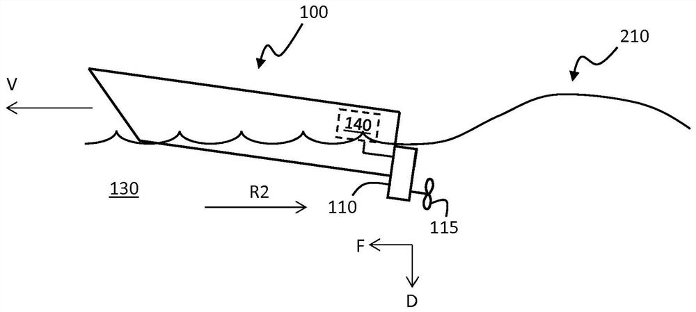
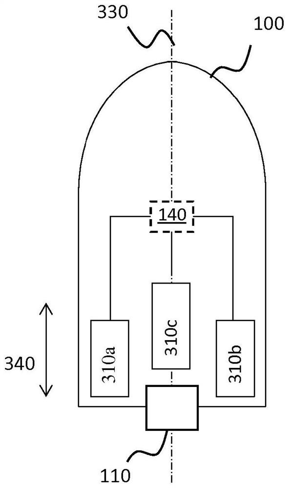
[0028] figure 1 A marine vessel 100 is schematically shown moving in water 130 . The marine vessel may for example be a power boat for wake sports, ie a smaller boat or a leisure craft. The vessel moves in water 130 using a propulsion unit 110 . figure 1 The propulsion unit 110 shown in is an exemplary propulsion unit comprising a propeller 115 . However, it should be understood that the techniques disclosed herein are also applicable to...


PUM


Abstract

The present invention relates to a method for controlling a propulsion operation of a propulsion unit to reach the desired speed of a marine vessel. The method comprises obtaining a target speed configuration indicating the desired speed of the marine vessel, obtaining a current speed value associated with a current speed of the marine vessel, obtaining a fill level value associated with a fill level of one or more ballast tanks of the marine vessel, and controlling the propulsion operation of the propulsion unit to reach the desired speed based on the target speed configuration, the current speed value, and on the fill level value.

Description

technical field [0001] The present disclosure relates to the control of propulsion units (eg combustion engines and electric motors) used to power marine vessels (eg recreational craft). Background technique [0002] When operating a marine vessel, it is sometimes desirable to configure the speed of the marine vessel to be automatically achieved and maintained by the speed control function. Global Positioning System (GPS) based speed control functions are known. The user enters a desired speed into the system and the automatic speed control unit then compares the desired speed with the vessel's current speed using speed data obtained from the GPS system. The control unit then controls the propulsion operation of the ship to achieve and maintain said desired speed by adjusting the current speed to match said desired speed. [0003] Speed ​​control functions are particularly useful when implemented in power boats for wake sports such as wakeboarding, wakesurfing, wakesurfing...

Claims


Application Information

Patent Timeline
Patent Type & Authority Applications(China)
IPC IPC(8): B63H21/21B63H20/10B63B34/00
CPCB63H20/10B63H21/21B63H2021/216B63B34/00B63B79/40B63B79/10B63B13/00B63H21/14B63H21/17B63H25/00
Inventor 埃里克·格利克松马蒂亚斯·林德堡
Owner CPAC SYST
Learn More