Mobile telephone and operation control method therefor

Inactive Publication Date: 2005-04-07
NEC CORP
View PDF12 Cites 17 Cited by
  • Summary
  • Abstract
  • Description
  • Claims
  • Application Information

AI Technical Summary

Benefits of technology

[0009] It is an object of the present invention to provide a mobile telephone and an operation control method therefor which

Problems solved by technology

When television broadcasting is received by a mobile telephone as described in JP-8-162909-A, problems can occur because of high power consumption when the television receiver unit is operating.
Specifically, in mobile telephones having a television receiving function, battery capacity is rapidly consumed when the television receiving function is used.
It is therefore contemplated that certain telephone capabilities, which are ba

Method used


Image

  • Mobile telephone and operation control method therefor
  • Mobile telephone and operation control method therefor
  • Mobile telephone and operation control method therefor

Examples


Embodiment Construction

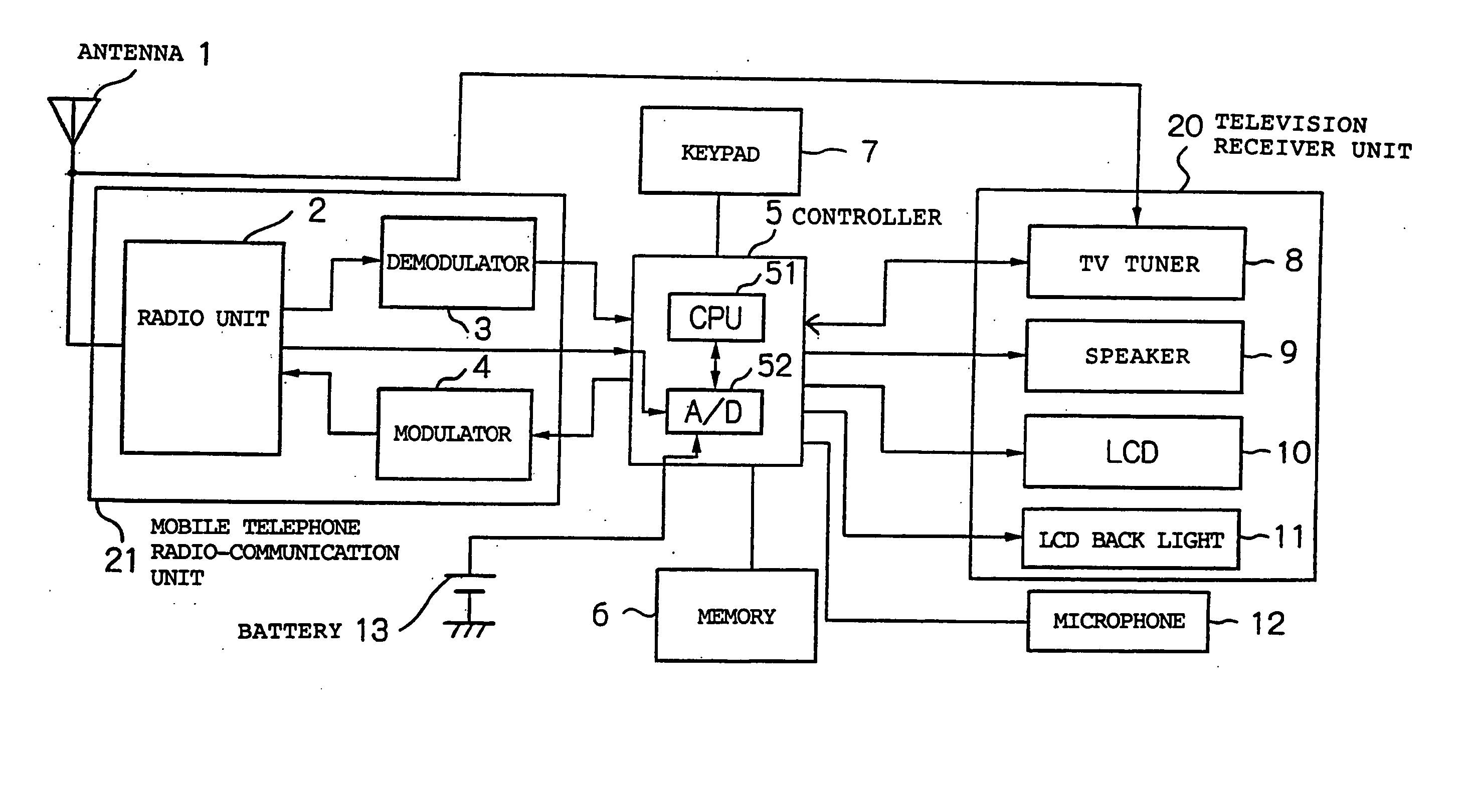
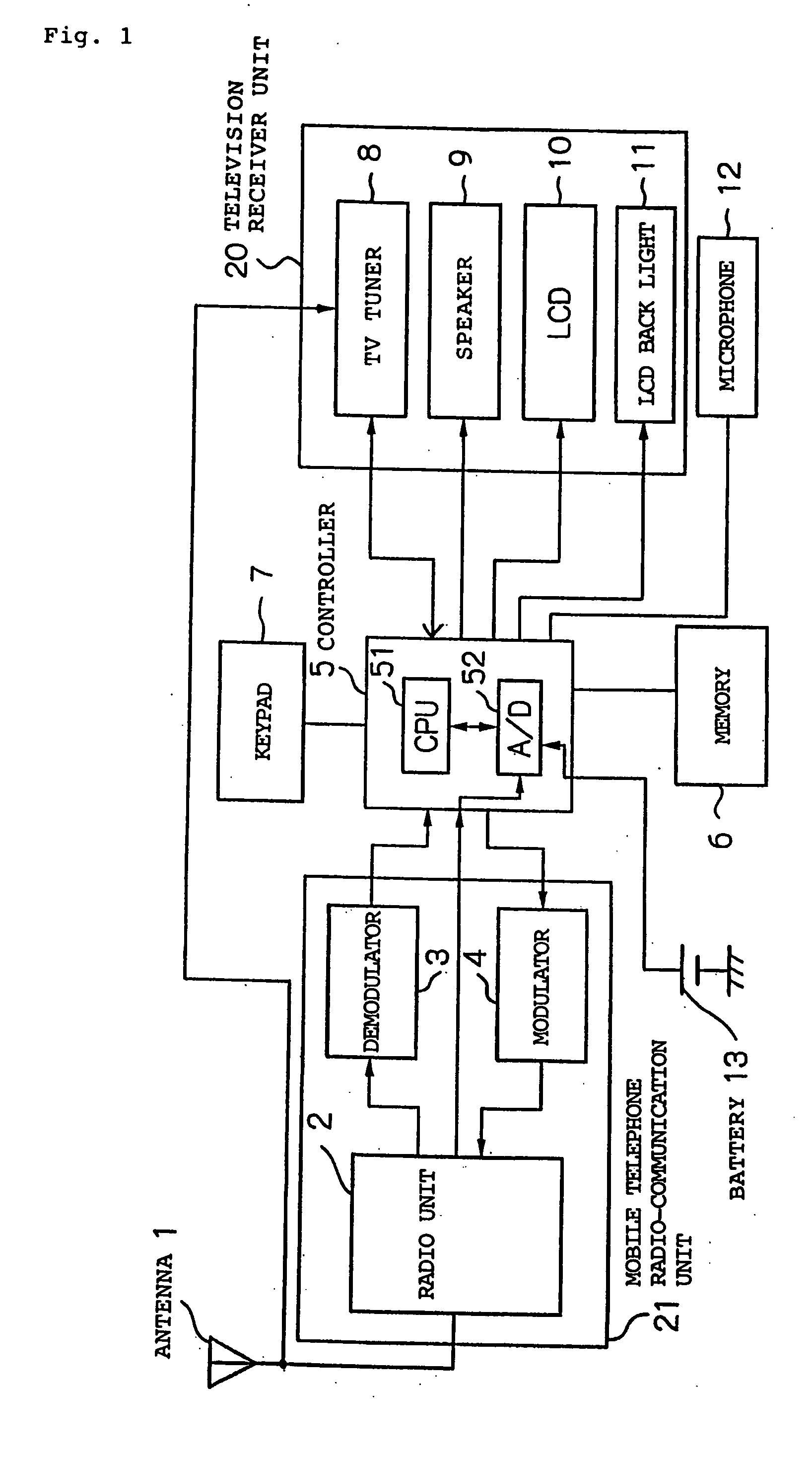
[0026]FIG. 1 is a block diagram illustrating a mobile telephone according to one embodiment of the present invention.

[0027] In FIG. 1, the mobile telephone comprises antenna 1, controller 5, memory 6, keypad 7, microphone 12, television receiver unit 20, and mobile telephone radio-communication unit 21.

[0028] Controller 5 includes CPU 51 and A / D converter 52. CPU 51 controls the operation of controller 5.

[0029] Television receiver unit 20 comprises TV (television) tuner 8, speaker 9 as an audio generator, LCD 10, and LCD back light 11.

[0030] Mobile telephone radio-communication unit 21 includes radio unit 2, demodulator 3, and modulator 4. The mobile telephone illustrated in FIG. 1 is powered by battery 13 for its operations.

[0031] Antenna 1 receives a mobile telephone signal transmitted from a base station (not shown). Radio unit 2 amplifies the mobile telephone signal received by antenna 1. Demodulator 3 demodulates the mobile telephone signal amplified by radio unit 2. Contr...


PUM


Abstract

A CPU limits the operation of a television receiver unit, and permits the operation of a mobile telephone radio-communication unit when a battery's voltage is lower than the threshold (operation control threshold) stored in memory.

Description

BACKGROUND OF THE INVENTION [0001] 1. Field of the Invention [0002] The present invention relates to a mobile telephone and an operation control method therefor, and more particularly, to a mobile telephone including a television receiver unit and a mobile telephone radio-communication unit, and an operation control method therefor. [0003] 2. Description of the Related Art [0004] In recent years, mobile telephones have been proposed that are equipped with a variety of additional functions. [0005] JP-8-162909-A discloses a mobile telephone that has a function of receiving broadcast programs of television, radio or the like. [0006] JP-2002-354375-A discloses techniques related to a reduction in power consumption of a device having a television receiver unit. Specifically, JP-2002-354375-A describes that a television receiving function and a radio receiving function are limited step by step based on the remaining amount of battery at the time the device is powered on. [0007] When telev...

Claims


Application Information

Patent Timeline
IPC IPC(8): H04M1/72403H04B1/16H04B7/26H04M1/00H04M1/21H04M1/73H04N5/63H04W52/02H04W88/02
CPCH04M1/72522H04W52/0264H04N21/4436H04N21/41407Y02D30/70H04M1/72403
Inventor HIGUCHI, NORIHIKO
Owner NEC CORP
Why Eureka
Try Eureka