
Measurement method and device for activating interfrequency handover in a wireless telecommunication network

a wireless telecommunication network and inter-frequency handover technology, applied in the direction of transmission monitoring, wireless commuication services, electrical equipment, etc., can solve the problems of inability to complete operation, inability to and low power efficiency of linear amplifiers, so as to avoid interference, maintain the communication capacity of terminal equipment, and reduce the risk of disconnection

Inactive Publication Date: 2006-05-09
NOKIA SOLUTIONS & NETWORKS OY
View PDF7 Cites 18 Cited by
  • Summary
  • Abstract
  • Description
  • Claims
  • Application Information

AI Technical Summary

Benefits of technology

[0009]According to this invention, a terminal equipment is able to provide a handover information signal that determines whether a handover to an alternative communication channel will occur. The terminal equipment accomplishes this by comparing the adjacent channel interference to the terminal equipment's own communication channel power, without any need for the terminal equipment to visit, monitor, or directly measure the adjacent channel being used by another base station. In other words, a terminal equipment is able to avoid adjacent channel interference, and thus the likelihood of disconnection, by switching communication to an alternative communication channel, for example an alternative frequency channel. The mobile terminal is able to use the communication channel unhindered, up until the handover.
[0010]In addition to avoiding interference and reducing risk of disconnection, the present invention is able to substantially maintain the terminal equipment's communication capacity, without requiring any major additional parts such as an additional receiver. According to this invention, the terminal equipment is able to compare adjacent channel power to communication channel power by examining the strength of a received signal before filtering the received signal and then again examining the strength of the received signal after filtering.
[0011]When the adjacent channel power becomes so great with respect to the communication channel power that there may be a risk of disconnection, a handover is requested which may be a frequency handover (that request may originate either in the mobile device or on the network side). A frequency handover is to a different frequency with the same base station, or it may be to a different frequency with a different base station, although in the latter case it may be necessary that the base stations share the same network operator. In either case, the present invention allows a more efficient handover decision procedure. Instead of the terminal equipment testing signal strengths on different frequencies or channels that are associated with different base stations, the terminal equipment of the present invention is capable of deducing adjacent signal strength based upon the effects of adjacent channel interference. Note that the terms adjacent channel power and adjacent channel interference will be used interchangeably throughout this specification, because, even if these two things are not identical to each other, they can be deduced from each other (i.e. each can be regarded as a function of the other).
[0012]The method and device of the invention thus have several advantages. The timing of interfrequency handover can be optimally selected without interfrequency monitoring which would detract from normal communication capacity on the communication channel. Also, no costly additions to the terminal equipment, such as an additional receiver, are required in order to optimize interfrequency handover. Furthermore, the invention facilitates interfrequency handover in situations where the handover is from one base station to another, in addition to the situation where the terminal equipment maintains communication with the same base station both before and after interfrequency handover.

Problems solved by technology

If the transmitter is nonlinear there will be interference outside the frequency band allocated for signal transmission, such interference being called adjacent channel interference.
Linear amplifiers cause only a little interference to adjacent frequency bands, but the power efficiency of linear amplifiers is low, and that is why some nonlinearity is often tolerated even though adjacent channel interference may result.
However, adjacent channel attenuation (selectivity) by the receiver is always limited, and cannot operate with complete success when adjacent channel interference becomes large.
In some situations, adjacent channel interference increases to such an extent that the connection may be disconnected.
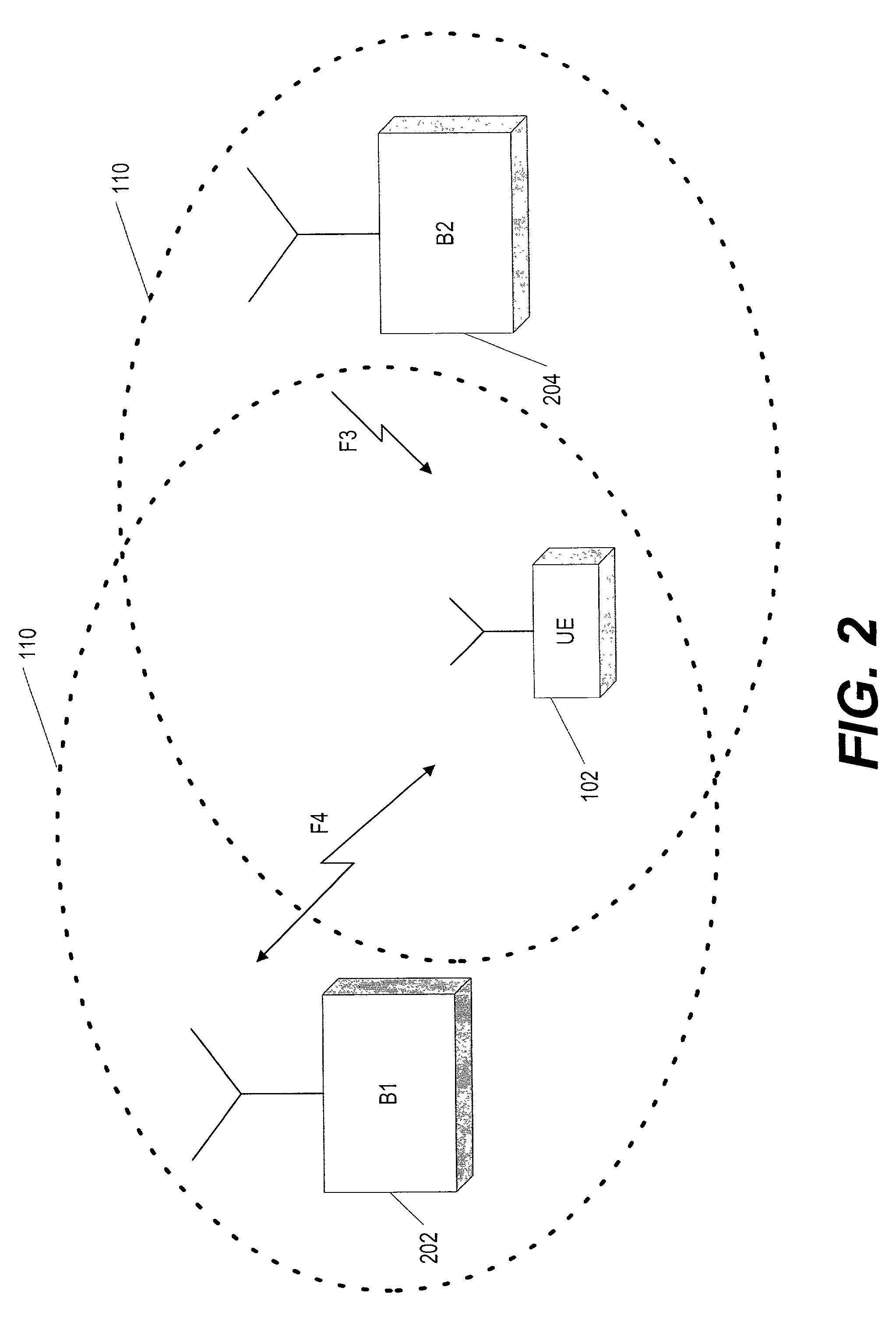
As the interference becomes stronger, there is a risk of the connection between the UE 102 and B1 202 being disconnected.
The purpose of the measurements is to search for handover candidates having a strong received downlink signal, but this procedure becomes problematic in the aforementioned situation where a candidate base station 204 is located on another frequency to which the terminal equipment 102 cannot perform a handover.
Furthermore, the process of directly measuring signal strengths from different base stations 114 is problematic because, even if that process occurs only at specific intervals rather than continuously, the process may intermittently detract from the terminal equipment's normal communication capacity.
However, this method does not take into account the interference to the terminal equipment's own connection, which means that the handover is not carried out in the best possible manner for the terminal equipment since the call may be blocked before the handover is completed.
However, that type of arrangement is problematic because a terminal equipment 102 will have lower communication capacity due to interfrequency monitoring, inasmuch as the terminal equipment 102 must regularly shift to another frequency for purposes of signal strength measurement.
This problem of capacity loss can be alleviated by employing a second receiver within the same terminal equipment 102, but a second receiver would entail significant increase in cost.

Method used


Image

  • Measurement method and device for activating interfrequency handover in a wireless telecommunication network
  • Measurement method and device for activating interfrequency handover in a wireless telecommunication network
  • Measurement method and device for activating interfrequency handover in a wireless telecommunication network

Examples


Embodiment Construction

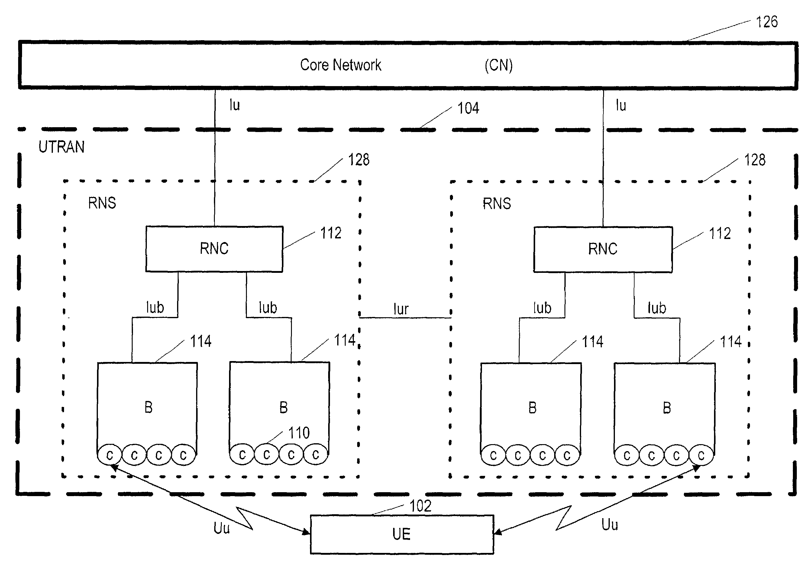
[0020]An embodiment of the best mode of the present invention can be implemented in the wireless telecommunications network environment shown by FIGS. 1 and 2. The present invention optimizes the air interface (Uu) between user equipment 102 and base stations 114 (base stations are also called Node B's in UMTS). The user equipment 102 of the present invention is capable of optimizing the interface Uu by avoiding the adjacent channel interference F3 shown in FIG. 2, and the terminal equipment 102 is thus able to reduce disconnections caused by the adjacent channel interference. This optimization method is implemented while the terminal equipment 102 and the base station 202 are communicating via a communication channel (F4), instead of involving interruptions of communication.

[0021]The method is depicted by the flow chart of FIG. 3. A received signal has already been processed to some extent by the terminal equipment 102 (this processing may include some filtering), but has not yet r...


PUM


Abstract

A method and device for avoiding adjacent channel interference and reducing disconnections caused thereby, during communication between a mobile device and a base station in a wireless telecommunications network. The mobile device measures the strength of a received signal before the signal enters one or more selected filters, and compares the strength of the signal after the filtering, in order to estimate a power ratio of the adjacent channel interference to communication channel power. If the power ratio is greater than a threshold, then a handover is requested to an alternative communication channel available between the mobile device and either the base station or another base station.

Description

TECHNICAL FIELD OF THE INVENTION[0001]The invention relates generally to the field of interference avoidance in a wireless telecommunications network, and relates more particularly to interfrequency handover in order to prevent disconnections caused by adjacent channel interference.BACKGROUND ART[0002]The prior art and related art arrangements occur in the context of a larger wireless telecommunications system, as exemplified by FIG. 1 which shows the structure of a wireless system according to the Universal Mobile Telecommunications System (UMTS is synonymous with WCDMA or wideband code division multiple access). As can be seen in FIG. 1, the UMTS architecture consists of user equipment 102 (UE which is herein synonymous with “mobile device” and “terminal equipment”), the UMTS Terrestrial Radio Access Network 104 (UTRAN), and the Core Network 126 (CN). The air interface between the UTRAN and the UE is called Uu, and the interface between the UTRAN and the Core Network is called Iu....

Claims


Application Information

Patent Timeline
IPC IPC(8): H04Q7/20H04Q7/00H04B17/00H04W36/08H04W36/20
CPCH04W36/20H04B17/382H04B17/309H04W36/08H04B17/318H04B17/354
Inventor KUIRI, TAPIOLILJA, HARRINUMMINEN, JUSSIJANSEN, KAJHAAPOJA, SAMI
Owner NOKIA SOLUTIONS & NETWORKS OY
Learn More