Diesel particulate filter control

a technology of particulate filter and diesel, which is applied in the direction of electrical control, machines/engines, mechanical equipment, etc., can solve the problems of reducing the ability of the engine control system to differentiate, reducing the sensitivity of the electrical sensor to a degraded dpf, and reducing the ability to distinguish between a degraded dpf and a marginal dpf. , to achieve the effect of reducing the amount of particulate matter emissions, reducing

Active Publication Date: 2011-06-09
FORD GLOBAL TECH LLC
View PDF12 Cites 18 Cited by
  • Summary
  • Abstract
  • Description
  • Claims
  • Application Information

AI Technical Summary

Benefits of technology

[0002]Emission control devices, such as diesel particulate filters (DPF), may reduce the amount of particulate matter emissions (such as, soot) from a diesel engine by trapping the particles. Such devices may be regenerated during engine operation to decrease the amount of trapped particulate matter (for example, by burning) and maintain the collection capacity of the device. To meet stringent federal government emissions standards, regeneration operations and DPF functionality may be tightly controlled and regularly assessed.
[0004]However, the inventor herein has recognized issues with such an approach. As one example, the use of resistive sensing-based particulate matter (PM) sensors reduces the ability of an engine control system to differentiate between a degraded filter and a degraded regeneration operation. As such, commonly used PM sensors may be configured to detect the presence of PMs electrically, based on a change in resistance or capacitance across an electrical circuit. Such sensors may have a “dead-band” during which PMs may have to accumulate before the sensor is able to respond. This additional time required to detect PMs may reduce the electrical sensor's sensitivity to a degraded DPF. Similarly, relatively small differences in resistance may reduce the ability to distinguish between a degraded DPF and a marginal DPF. Thus, in one instance, the system may not be able to identify DPF degradation.
[0005]As another example, the use of input from CO2 sensors that sense exhaust CO2 levels may also reduce the system's ability to accurately estimate the soot load on the filter due to an indirect correlation between filter soot levels and exhaust CO2 levels. Since the exhaust CO2 level is more representative of combustion conditions, a soot load may be inferred but not accurately determined.
[0010]In this way, the presence of soot in engine exhaust may be detected by oxidizing the soot to generate CO2, and by using downstream CO2 sensors to provide a more direct and more precise estimate of exhaust soot levels, in addition to their use in estimating exhaust CO2 levels. By enabling an accurate, real-time estimate of exhaust soot levels, filter regeneration may be better controlled. Additionally, the higher sensitivity of the CO2 gas sensors may reduce the “dead-band” effect of resistive sensors and provide higher resolution between signals. This higher resolution may improve the ability to identify a degraded particulate filter, and further to distinguish between a degraded filter and reduced filter functionality. Similarly, the higher resolution may improve the ability to distinguish between a degraded filter and a degraded regeneration operation. By improving regeneration and filter diagnostics, the quality of exhaust emissions maybe improved.

Problems solved by technology

However, the inventor herein has recognized issues with such an approach.
As one example, the use of resistive sensing-based particulate matter (PM) sensors reduces the ability of an engine control system to differentiate between a degraded filter and a degraded regeneration operation.
This additional time required to detect PMs may reduce the electrical sensor's sensitivity to a degraded DPF.
Similarly, relatively small differences in resistance may reduce the ability to distinguish between a degraded DPF and a marginal DPF.
Thus, in one instance, the system may not be able to identify DPF degradation.
As another example, the use of input from CO2 sensors that sense exhaust CO2 levels may also reduce the system's ability to accurately estimate the soot load on the filter due to an indirect correlation between filter soot levels and exhaust CO2 levels.

Method used


Image

  • Diesel particulate filter control
  • Diesel particulate filter control
  • Diesel particulate filter control

Examples


Embodiment Construction

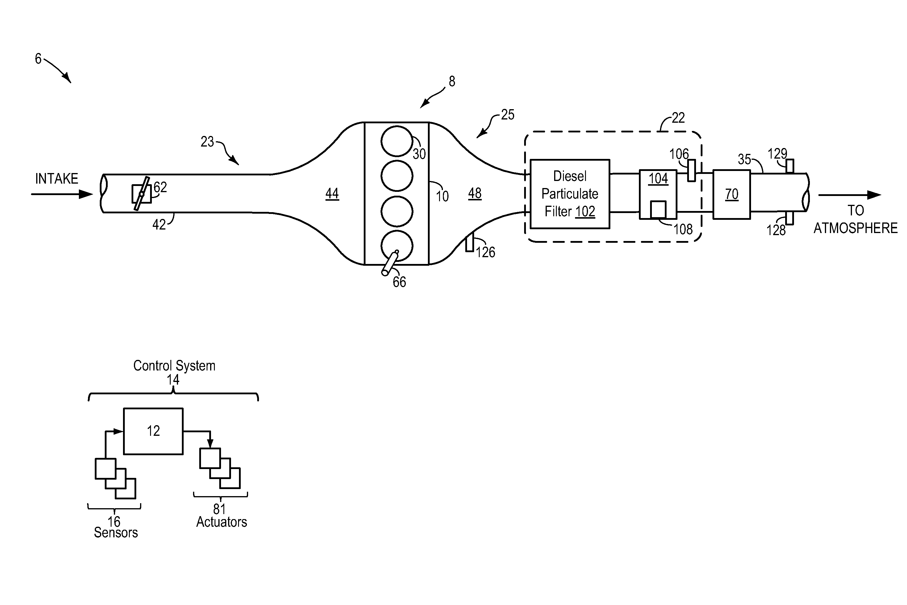
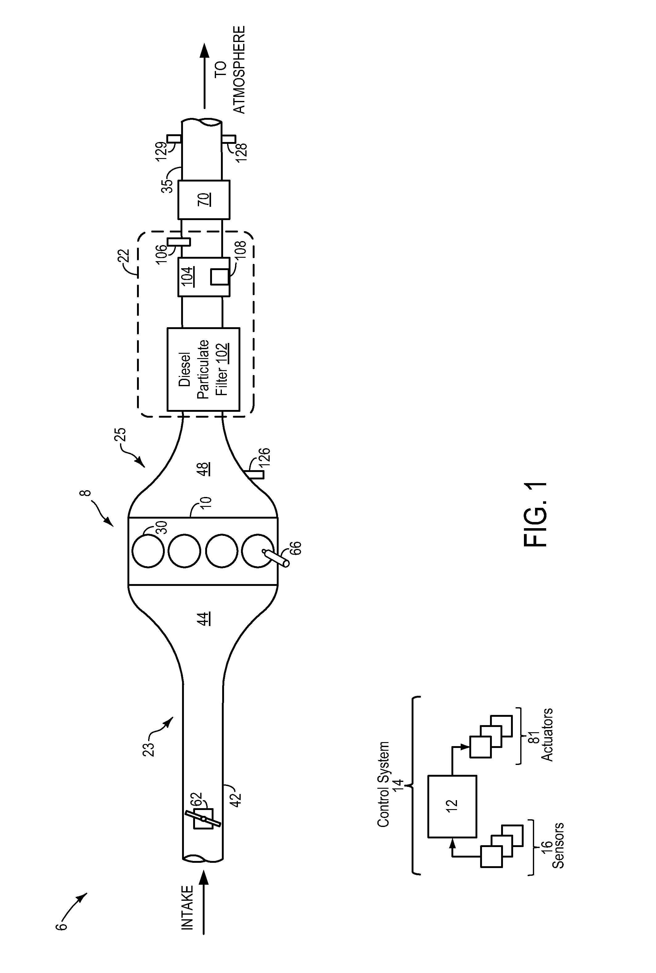
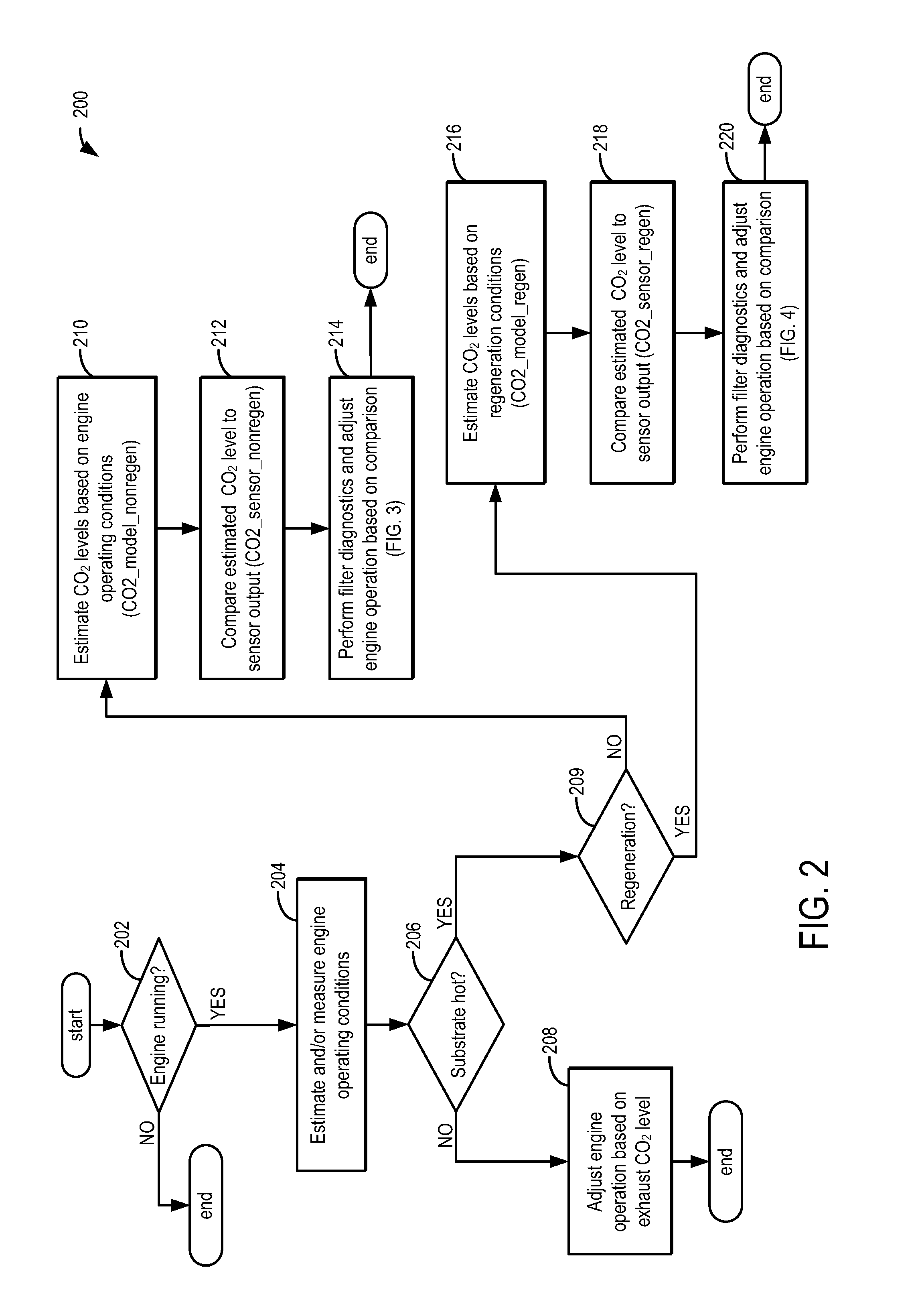
[0014]The following description relates to systems and methods for controlling a particulate matter retaining system, such as the diesel particulate matter (PM) retaining system of FIG. 1. As shown therein, the PM retaining system may include a diesel particulate filter, a filter substrate, and a CO2 gas sensor positioned downstream of the filter and the substrate. As shown in FIG. 2, when the substrate is not heated, that is, the substrate is not enabled for oxidizing, the CO2 sensor may be used to estimate exhaust CO2 levels and adjust engine operation based on the estimated value. When the substrate is enabled for oxidizing (for example, when the substrate is electrically heated by a dedicated substrate heater, or non-electrically heated by hot exhaust gas), post-filter exhaust may be passed over the heated substrate and exhaust PMs, if present, may be oxidized to CO2 using oxygen from the exhaust gas on the substrate upstream of the CO2 sensor. Herein, the CO2 sensor may be used...


PUM


Abstract

Methods and systems are provided for managing particulate emissions in an engine including a particulate filter and a CO2 sensor downstream of the filter. A CO2 sensor may be used to infer the presence of particulate matter in the exhaust, downstream of the filter. By sensing particulate matter in the post-filter exhaust, filter degradation may be identified.

Description

FIELD[0001]The present description relates to particulate matter purifying systems for internal combustion engines, such as diesel engines and gasoline engines.BACKGROUND AND SUMMARY[0002]Emission control devices, such as diesel particulate filters (DPF), may reduce the amount of particulate matter emissions (such as, soot) from a diesel engine by trapping the particles. Such devices may be regenerated during engine operation to decrease the amount of trapped particulate matter (for example, by burning) and maintain the collection capacity of the device. To meet stringent federal government emissions standards, regeneration operations and DPF functionality may be tightly controlled and regularly assessed.[0003]One example approach for controlling diesel particulate filters is illustrated by Stewart et al. in U.S. Pat. No. 7,155,334. Therein, an engine controller controls filter regeneration based on inputs received from sensors, such as particulate matter sensors and / or carbon dioxi...

Claims


Application Information

Patent Timeline
Patent Type & Authority Applications(United States)
IPC IPC(8): F01N3/00F01N9/00
CPCF01N3/027F01N9/002F01N11/00F01N2550/04F01N2560/022F01N13/0093F02D41/0235F02D41/029F02D41/1446F02D41/1452Y02T10/47F01N2900/1402Y02T10/40
Inventor PARNIN, CHRISTOPHER
Owner FORD GLOBAL TECH LLC
Why Eureka
Try Eureka