Mobile terminal circuit including an RFID tag and wireless identification method using the same

a mobile terminal and wireless identification technology, applied in the field of radio frequency identification (rfid) tags, can solve the problems of inability to propose the connection between the smart card and the mpu or its peripheral circuit, inability to predict the combination of the rfid tag circuit and the terminal circuit, and difficulty in achieving the miniaturization of the mobile terminal

Active Publication Date: 2005-04-07
SAMSUNG ELECTRONICS CO LTD
View PDF15 Cites 69 Cited by
  • Summary
  • Abstract
  • Description
  • Claims
  • Application Information

AI Technical Summary

Problems solved by technology

In addition, since combination between the RFID reader circuit and the terminal circuit is not disclosed, one skilled in the art cannot predict a combination of the RFID tag circuit and the terminal circuit in the light of the connection between the RFID reader circuit and the terminal circuit.
However, the reference fails to propose the connection between the smart card and the MPU or its peripheral circuit.
However, the conventional technologies have the following disadvantages.
First, it is difficult to achieve miniaturization of a mobile terminal.
Second, since the conventional RFID tag does not have its own power supply, electromotive force induced from a carrier of an RFID reader is used as electric power.
In this case, it is difficult to provide sufficient electric power to the RFID tag in an environment where an air environment between the RFID reader and the RFID tag is influenced by noises.
|As a result, the RFID tag may operate incorrectly.

Method used


Image

  • Mobile terminal circuit including an RFID tag and wireless identification method using the same
  • Mobile terminal circuit including an RFID tag and wireless identification method using the same
  • Mobile terminal circuit including an RFID tag and wireless identification method using the same

Examples


first embodiment

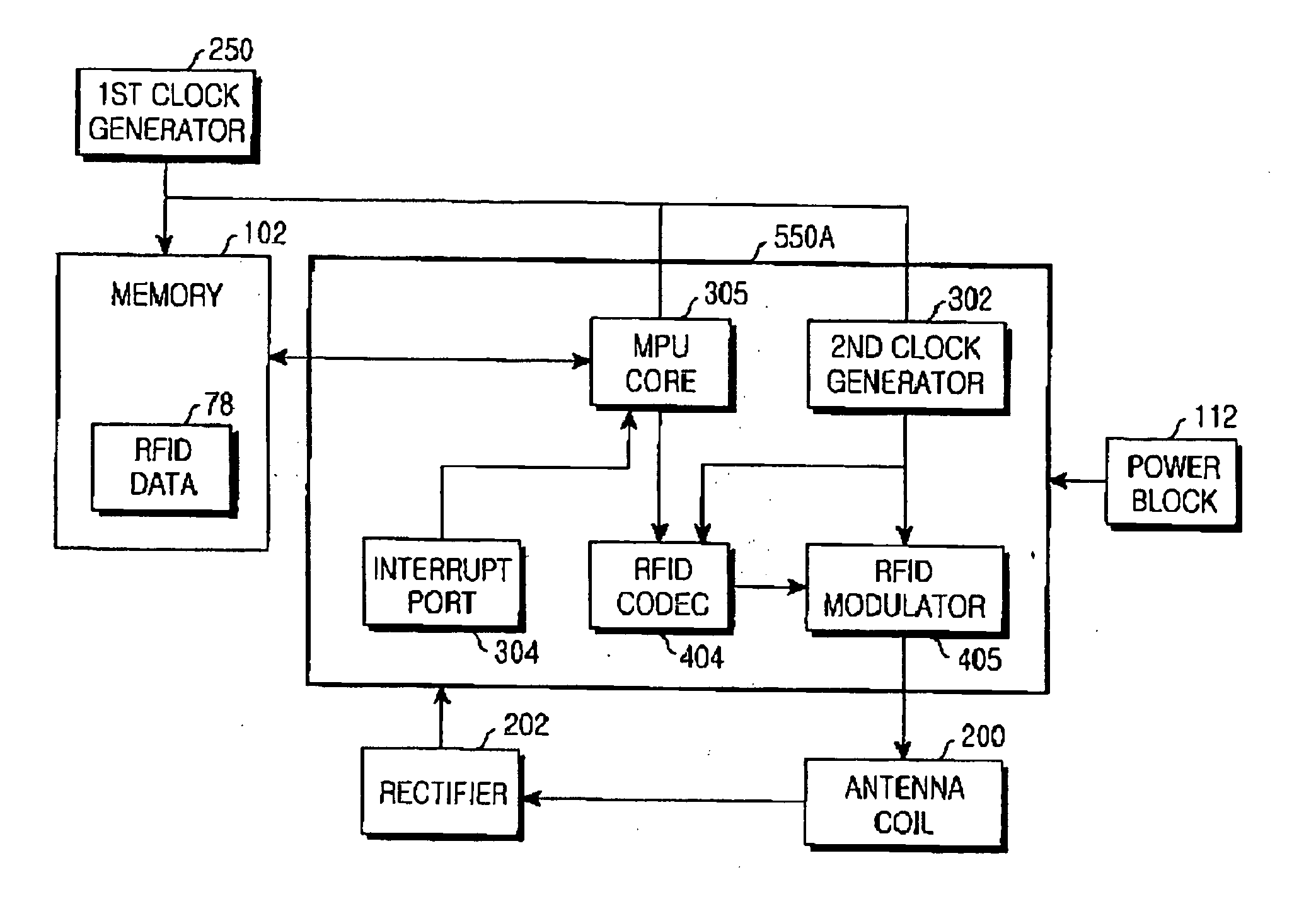
[0036]FIG. 4 is a block diagram illustrating a structure of a mobile terminal including an RFID tag according to the present invention. It should be noted that known elements of the mobile terminal other than the elements related to the connection between the mobile terminal and the RFID tag are not illustrated in the drawing for simplicity.

[0037] According to a first embodiment of the present invention, referring to FIG. 4, an MPU 550A of the mobile terminal includes an RFID codec 404 and an RFID modulator 405, which are elements of an RFID tag. Moreover, the memory portion 102 of the mobile terminal additionally stores RFID data 78 together with mobile terminal protocol data.

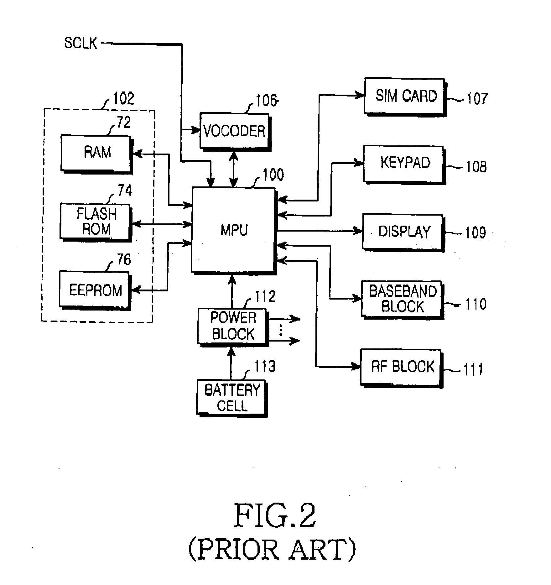
[0038] Referring to FIG. 2, the EEPROM 76 of the mobile terminal is an element of the memory portion 102. Commonly, the EEPROM 76 stores initial setup values of the RF block 111, the display 109 and a voice volume, a user defined value such as address book data, and WAP (Wireless Application Protocol) data. H...

second embodiment

[0045]FIG. 5 is a block diagram illustrating a structure of a mobile terminal including an RFID tag according to the present invention, in which main elements of the RFID tag are implemented with one IC (Integrated Circuit). It should be noted that known elements of the mobile terminal other than the part related to the connection between the mobile terminal and the RFID tag are not illustrated in the drawing for simplicity.

[0046] As illustrated in FIG. 5, an RFID codec 404, an RFID modulator 405, a second clock generator 302, and an RFID memory 78 are implemented with one IC 600 (hereinafter, referred to as an “RFID chip” or “RFID module”), and various modifications are available. FIG. 6 illustrates an example of one modification.

[0047] In the structure of FIG. 1, the RFID tag has the rectifier 202 and the clock generator 201. However, in the second embodiment of the present invention, instead of the clock generator 201, the second clock generator 302 receives a system clock SCLK,...

third embodiment

[0050]FIG. 6 is a block diagram illustrating a structure of a mobile terminal including an RFID tag according to the present invention. Compared with the RFID tag illustrated in FIG. 5, the RFID tag illustrated in FIG. 6 excludes the RFID memory 78 from the RFID module 600, and stores RFID data in the memory portion 102 as described in conjunction with FIG. 4.

[0051] As can be appreciated from the foregoing description, the present invention can implement combination of an RFID tag and a mobile terminal while securing miniaturization of the mobile terminal and a stable operation of the RFID tag. In addition, the present invention minimizes the mobile terminal circuit by increasing generalization of elements in implementing the combination.


PUM


Abstract

A mobile terminal circuit for transmitting radio frequency identification (RFID) data to an RFID reader. The mobile terminal circuit comprises an antenna for communication with the RFID reader; a memory portion for storing RFID data together with mobile terminal protocol data; a codec for encoding the RFID data into RFID codec data; a modulator connected to the codec, for modulating the RFID codec data into RFID modulation data; a processor connected to the memory portion, for extracting RFID data stored in the memory portion and delivering the extracted RFID data to the codec; a detector connected to the antenna and the processor, for informing the processor of approach of the RFID reader; a first clock generator connected to the processor and the memory portion, for providing operation timing to the processor and the memory portion; and a second clock generator connected to the first clock generator, the codec and the modulator, for providing operation timing to the codec and the modulator.

Description

PRIORITY [0001] This application claims priority under 35 U.S.C. § 119 to an application entitled “Mobile Terminal Circuit Combined with RFID Tag and Wireless Identification Method Using the Same” filed in the Korean Intellectual Property Office on Oct. 7, 2003 and assigned Serial No. 2003-69669, the contents of which are incorporated herein by reference.BACKGROUND OF THE INVENTION [0002] 1. Field of the Invention [0003] The present invention relates generally to a radio frequency identification (RFID) tag, which is increasing in frequency of use and importance, and a widely-spread mobile terminal, and in particular, to a mobile terminal circuit including an RFID tag in one body and a wireless identification method using the same. [0004] 2. Description of the Related Art [0005] An RFID transponder, or an RFID tag, was developed by United States National Laboratory for Department of Agriculture for the purpose of identifying livestock. An electric code for identifying an animal is re...

Claims


Application Information

Patent Timeline
Patent Type & Authority Applications(United States)
IPC IPC(8): H04B5/02G06K7/00G06K19/07H04B1/59H04B7/26
CPCG06K19/0723G06K7/0008H04B1/59
Inventor JEI, DAE-GUNNPARK, SEO-YOUNG
Owner SAMSUNG ELECTRONICS CO LTD
Why Eureka
Try Eureka