
Method and means for variably transferring rotation energy

a technology of rotation energy and transmission method, which is applied in the direction of differential gearing, belt/chain/gearing, toothed gearing, etc., can solve the problems of limited transmission ratio, relatively poor efficiency of known gearbox and transmission based on the above mentioned principles, and limited transmission ratios. achieve the effect of ideally unlimited number of available transmission ratios, high theoretical efficiency and high functionality

Inactive Publication Date: 2005-04-07
HOLMSEN TRYGVE
View PDF3 Cites 5 Cited by
  • Summary
  • Abstract
  • Description
  • Claims
  • Application Information

AI Technical Summary

Benefits of technology

The continuously variable transmission according to the present invention avoids the shortages of existing gearboxes and transmission, as defined by the features stated in the claims.
Additionally the transmission according to the present invention provides a high theoretically efficiency, the number of available transmission ratios are ideally unlimited. Due to simplicity of its operational principle it is possible to implement the transmission according to the invention for practical use in applications resulting in higher functionality, radically lower complexity, weight, size and production-cost than comparable existing solutions.

Problems solved by technology

Known gearboxes and transmissions based on the above mentioned principles have limitations in respect to one ore more of the following.
In some cases only a relatively poor efficiency can be achieved.
Furthermore are available transmission ratios often limited.
In many cases is the response time relatively and unacceptable long.
Again other transmission has high complexity, high weight, large size and high production cost.

Method used


Image

  • Method and means for variably transferring rotation energy
  • Method and means for variably transferring rotation energy
  • Method and means for variably transferring rotation energy

Examples


Embodiment Construction

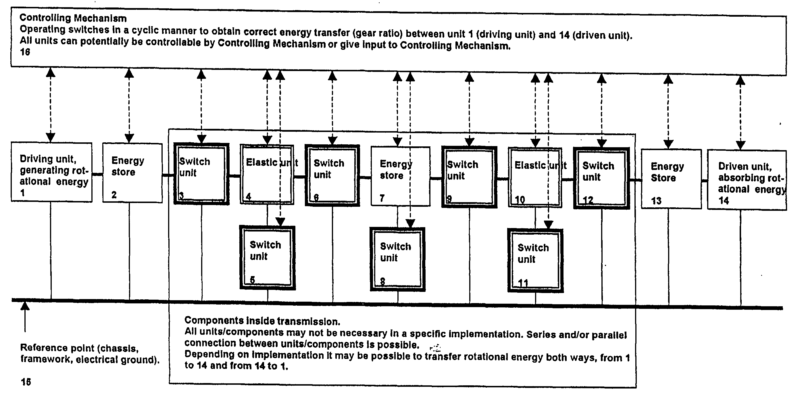
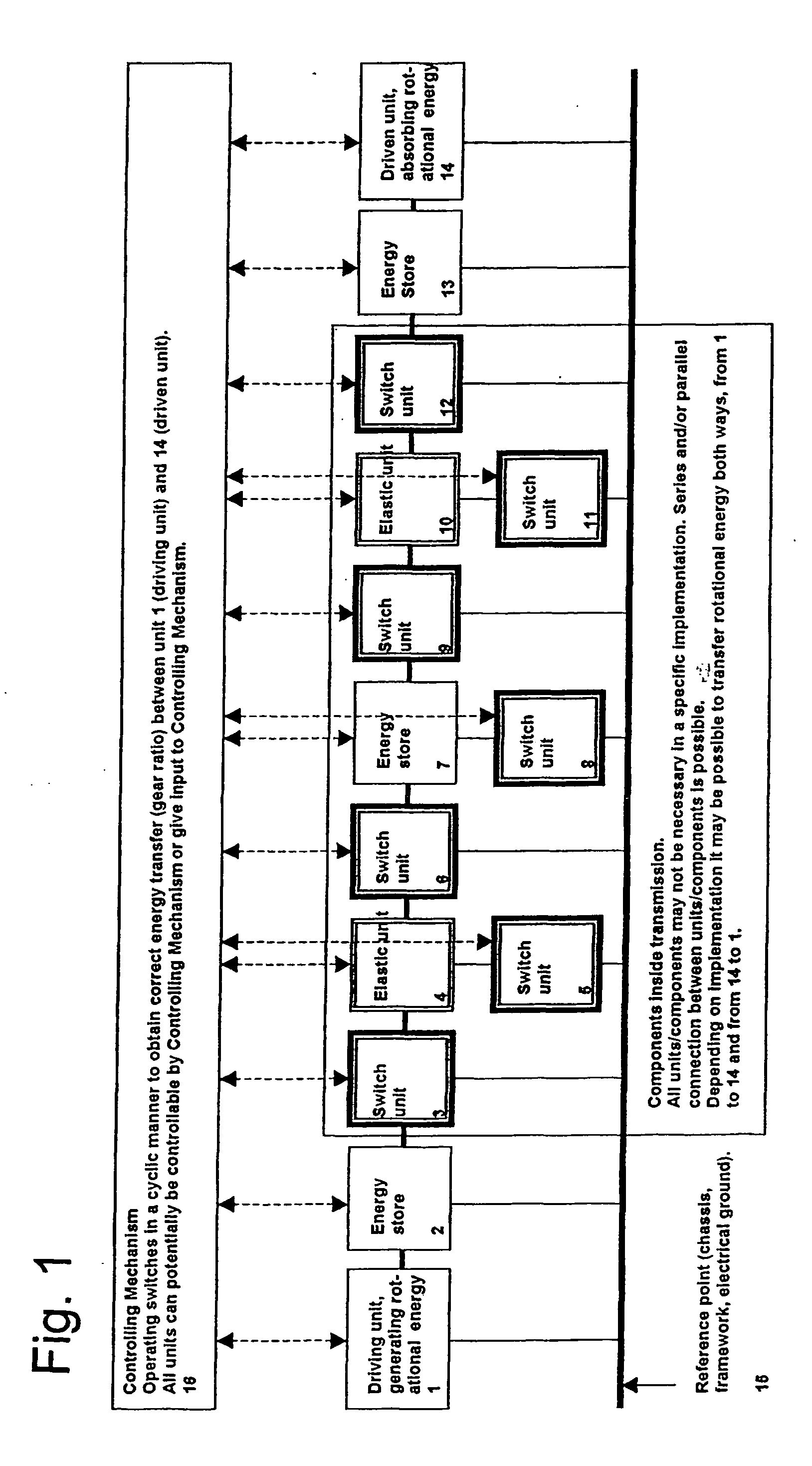
In general the operational pattern can easily be controlled by low cost computers contributing to highest overall functionality. In other implementations operational pattern can be part of the construction it self.

The operational principle of the transmission is based on the use of elastic collisions, however, in order to implement the principle in a transmission one have to overcome several practical challenges.

FIG. 1 identifies the three main component categories in the present innovation. Not all units in FIG. 1 may be necessary, neither is the connection to reference point 15 necessary for all units. The categories are as follows: 1. Switch unit. A unit that can control energy transfer, which can be implemented in a number of ways using such as mechanical, hydraulic, pneumatic, magnetic or electric means. In order to be practical useful in the present invention switches 3, 5, 6, 8, 9, 11 and 12 has to satisfy the following four criterias: A. Energy associated by the operat...


PUM


Abstract

Method for transferring rotation energy from an input shaft to an output shaft at a continuously variable transmission ratio, whereby direct or indirect energy transfer between the shafts by means of at least one elastic collision involving at least one switch unit capable of controlling energy transfer satisfying the conditions of operating whithout absorbing much energy, operating very fast, operating with minimal internal friction or wear and operating without using friction as a major part in how energy is transferred, combined with the use of at least one elastic unit and optionally the use of energy store units, whereby all three unit categories and units may independently be implemented using mechanical, hydraulic, pneumatic, magnetic or electronic means.

Description

BACKGROUND OF THE INVENTION 1. Field of the Invention The present invention is related to a method and a transmission for continuously variable transmission. 2. Description of the Related Art Known transmission of the above type compromise gearboxes and transmissions which roughly can be grouped into ordinary gearboxes using a combination of cogwheels or toothed wheels, transmissions based on hydraulic torque converters and cogwheels or is toothed wheels, continuously variable transmissions using conic shafts, often in combination with different kind of belts and finally transmissions using energy transfer through variable momentum of inertia. Known gearboxes and transmissions based on the above mentioned principles have limitations in respect to one ore more of the following. In some cases only a relatively poor efficiency can be achieved. Furthermore are available transmission ratios often limited. In many cases is the response time relatively and unacceptable long. Other kno...

Claims


Application Information

Patent Timeline
IPC IPC(8): F16H33/02F16H3/02F16H33/06F16H37/02
CPCF16H33/02
Inventor HOLMSEN, TRYGVE
Owner HOLMSEN TRYGVE
Learn More