Control system for air-compressing apparatus

a control system and air compressor technology, applied in the direction of pump control, positive displacement liquid engine, fluid parameter, etc., can solve the problems of increasing the number of man-hours, waste of electric power, and unnecessarily large number of compressors operated, so as to achieve the effect of increasing the rate, and reducing the power consumption of the air compressor

Active Publication Date: 2010-05-25
HITACHI LTD
View PDF18 Cites 22 Cited by
  • Summary
  • Abstract
  • Description
  • Claims
  • Application Information

AI Technical Summary

Benefits of technology

[0008]Accordingly, an object of the present invention is to provide a control system for an air-compressing apparatus that controls the discharge volume (flow rate) of the air-compressing apparatus according to the consumption of compressed air without using a flow sensor, thereby enabling the power consumption to be reduced.
[0020]According to a still further feature of the present invention, the control means operates all the air compressors when the pressure in the tank is lower than a predetermined lower limit pressure. Thus, when the pressure in the tank is excessively low, the tank pressure can be increased in a stroke, whereby it is possible to prevent a shortage of air in the tank, which is an unallowable situation.

Problems solved by technology

Therefore, there are cases where an unnecessarily large number of compressors are operated because the detected tank pressure has become lower than a predetermined control threshold value despite a very low consumption of compressed air from the tank.
In such cases, the electric power is consumed wastefully.
In this case, however, an extra flow sensor needs to be provided, and the installation of the flow sensor increases the number of man-hours.
Therefore, the production cost increases unfavorably.

Method used


Image

  • Control system for air-compressing apparatus
  • Control system for air-compressing apparatus
  • Control system for air-compressing apparatus

Examples


first embodiment

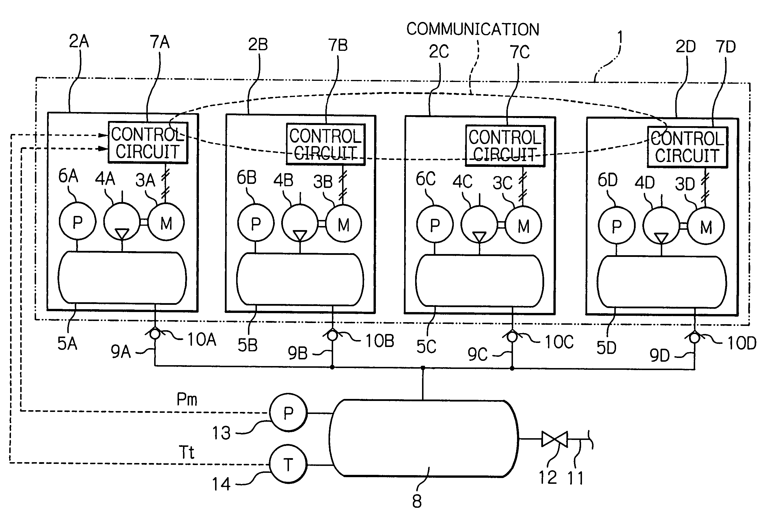
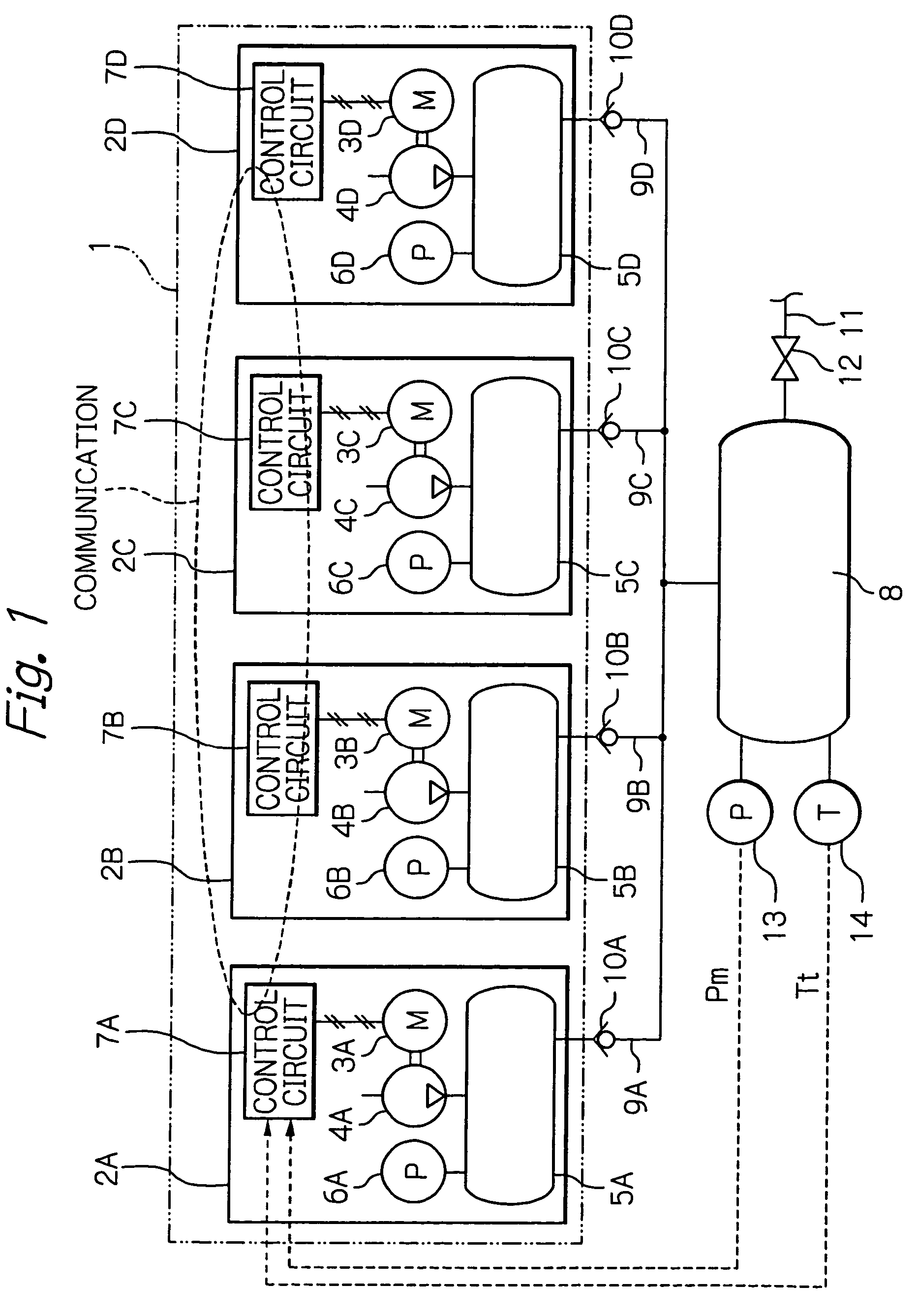
[0030]FIGS. 1 to 4 show the present invention. In the figures, an air-compressing apparatus 1 includes four compressors 2A to 2D. The compressor 2A consists essentially of an electric motor 3A, a compressor body 4A driven by the electric motor 3A, and a temporary storage tank 5A that temporarily stores compressed air discharged from the compressor body 4A. The other compressors 2B to 2D also have electric motors 3B to 3D, compressor bodies 4B to 4D, and temporary storage tanks 5B to 5D, respectively, as in the case of the compressor 2A. All the compressors 2A to 2D have the same discharge flow rate Fa to Fd [for example, Fa to Fd=605 (NL / min)].

[0031]The temporary storage tanks 5A to 5D have respective pressure sensors 6A to 6D attached thereto to detect pressures therein. Further, the compressors 2A to 2D are provided with respective control circuits 7A to 7D to control the start and stop of the electric motors 3A to 3D. The control circuits 7A to 7D have respective communication se...

second embodiment

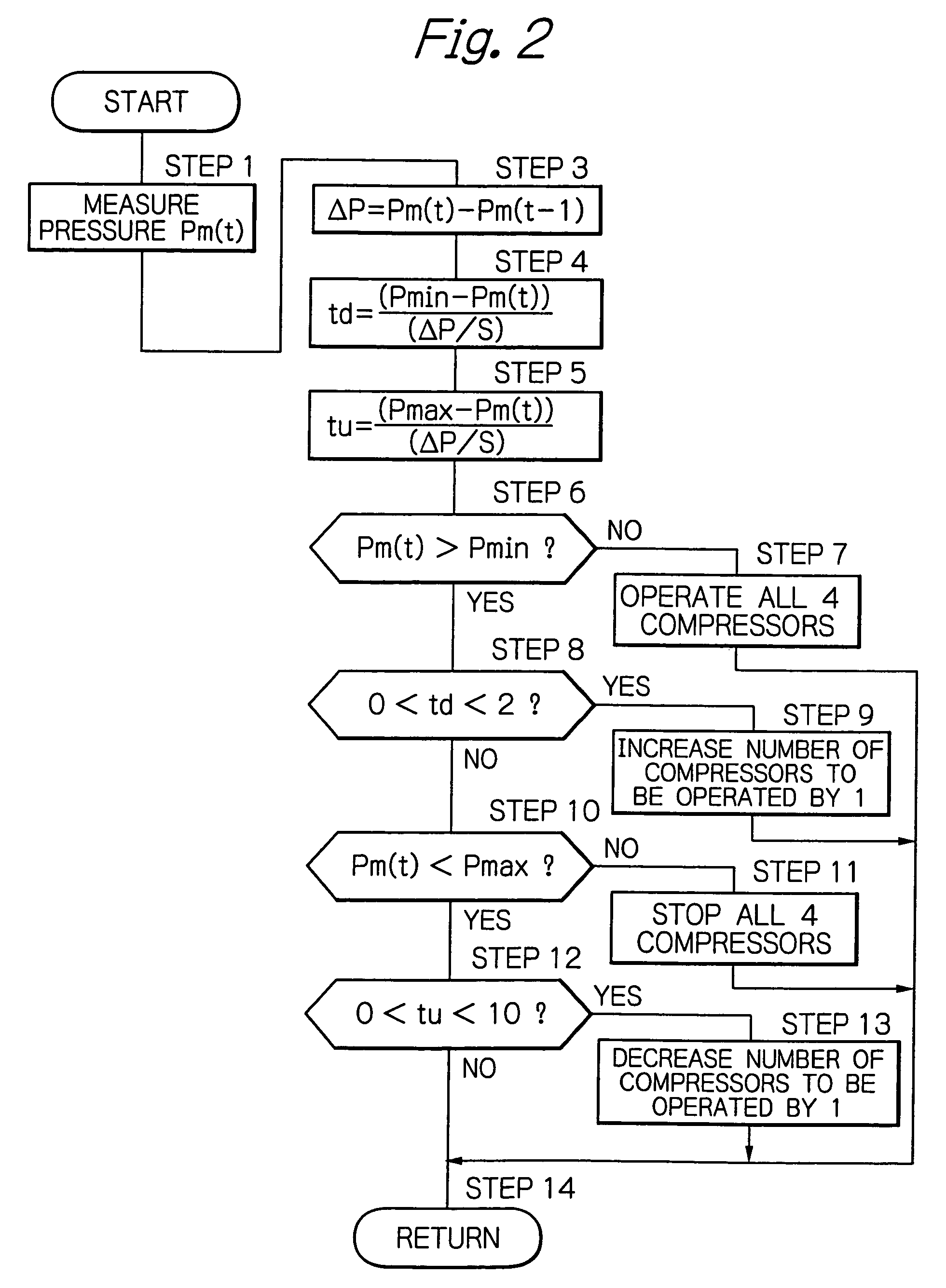
[0091]Thus, in the second embodiment, the number of compressors to be operated is increased or decreased according to the increasing rate or the decreasing rate of the pressure in the tank 8. As a result, the increasing rate or the decreasing rate is controlled to have a small value. Consequently, the supply and consumption of compressed air are controlled to values close to each other. Hence, the power consumption of the air-compressing apparatus 1 can be minimized.

[0092]At step 23, a compressor that is to be stopped is kept from stopping until a predetermined time duration has elapsed from the previous stopping time point of the compressor to be stopped. Accordingly, it is possible to prevent one compressor from repeating starting and stopping in a short period of time and hence possible to increase the service lifetime of the equipment.

[0093]It should be noted that step 23 in the second embodiment may be put before step 13 in the first embodiment.

[0094]A third embodiment of the p...

third embodiment

[0109]Thus, in the third embodiment, the threshold values for increasing or decreasing the number of compressors to be operated are changed according to the increasing rate or the decreasing rate of the pressure in the tank 8. As a result, the increasing rate or the decreasing rate is controlled to have a small value. Consequently, the supply and consumption of compressed air are controlled to values close to each other. Hence, the power consumption of the air-compressing apparatus 1 can be minimized.

[0110]Although in the air-compressing apparatus according to the foregoing embodiments the four compressors have the same discharge flow rate Fa to Fd, it should be noted that the present invention is not necessarily limited thereto. Each compressor may have a different discharge flow rate. In this case, even finer control can be achieved by appropriately combining the compressors with each other.

[0111]It is possible in the present invention to use reciprocating, rotary-screw, scroll, a...


PUM


Abstract

An air-compressing apparatus has four compressors individually supplying compressed air to a tank having a pressure sensor. The pressure sensor is connected to control circuits of the compressors. The control circuits compute times needed for the tank pressure to reach minimum and maximum pressures, respectively, of the tank by using the detected tank pressure and also using a tank pressure change value. The computed time values correspond to the consumption of compressed air. Thus, the control circuits can control the number of compressors to be operated according to the consumption of compressed air.

Description

BACKGROUND OF THE INVENTION[0001]1. Field of the Invention[0002]The present invention relates to a control system suitable for use in an air-compressing apparatus including, for example a plurality of compressors that individually supply compressed air to a tank.[0003]2. Description of Related Art[0004]A generally known type of air-compressing apparatus has a plurality of compressors connected in parallel to a tank (for example, see Japanese Patent Application Publication Nos. 2003-21072 and 2003-35273). The air-compressing apparatus is provided with a pressure sensor to measure the pressure in the tank. The pressure value detected with the pressure sensor is compared with a plurality of predetermined control threshold values to perform loading / unloading control and start / stop control of each compressor. With this system, the number of compressors to be operated is varied according to the pressure in the tank to adjust the discharge flow rate of compressed air supplied to the tank.[...

Claims


Application Information

Patent Timeline
Patent Type & Authority Patents(United States)
IPC IPC(8): F04B41/06F04B49/06
CPCF04B41/02F04B49/022F04B41/06F04B2205/05
Inventor HIRASAWA, TAKAHISAKAWASAKI, KAZUMASASHINDO, MANABUNAKAMURA, TOMOHIROCHIKUMA, HIROSHI
Owner HITACHI LTD
Why Eureka
Try Eureka