Charge control apparatus for vehicle

a technology for controlling apparatus and charging device, which is applied in the direction of battery/fuel cell control arrangement, secondary cell servicing/maintenance, battery/fuel cell propulsion, etc. it can solve the problems of increasing costs, prolong the charging time period, and avoid the shortage of charge electric energy at the charge stop time. , to achieve the effect of enhancing the required capacity of the heater

Active Publication Date: 2013-06-27
NISSAN MOTOR CO LTD
View PDF12 Cites 23 Cited by
  • Summary
  • Abstract
  • Description
  • Claims
  • Application Information

AI Technical Summary

Benefits of technology

[0007]Even in a case where a charge electric energy is reduced due to simultaneous implementation of the timer charge and the battery heating, the charge time period can be prolonged by advancing the charge start time, and shortage of a charge electric energy at the charge stop time can be avoided. Further, since the battery heating can be carried out during the timer charge, it is not necessary to enhance a required capacity of the heater, and therefore, an increased cost can be avoided.

Problems solved by technology

In a case where a large-capacity battery useable as a power source for travel of the vehicle is heated, there occurs a problem that a required capacity of the heater becomes higher to thereby cause an increased cost.

Method used


Image

  • Charge control apparatus for vehicle
  • Charge control apparatus for vehicle
  • Charge control apparatus for vehicle

Examples


embodiment 1

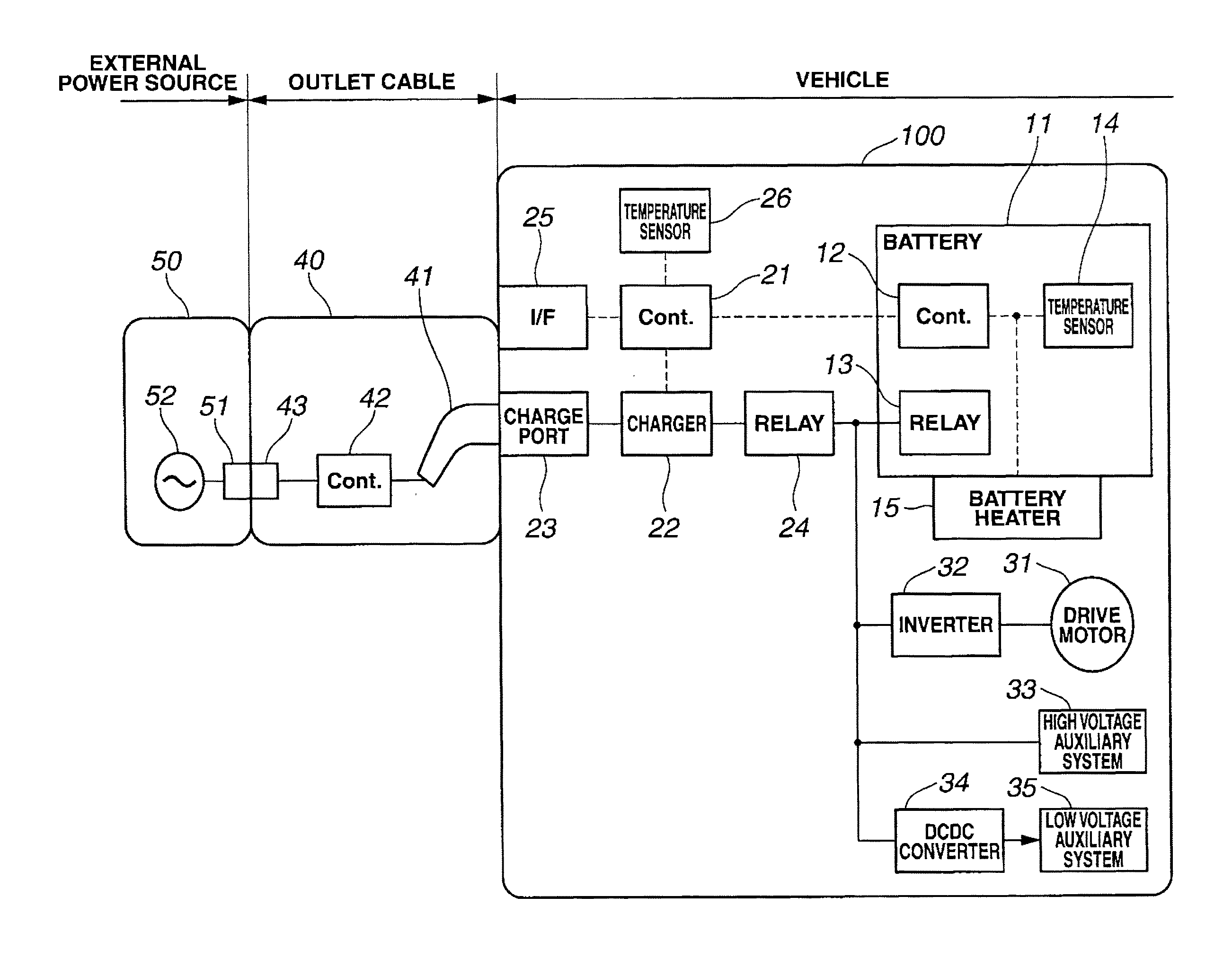
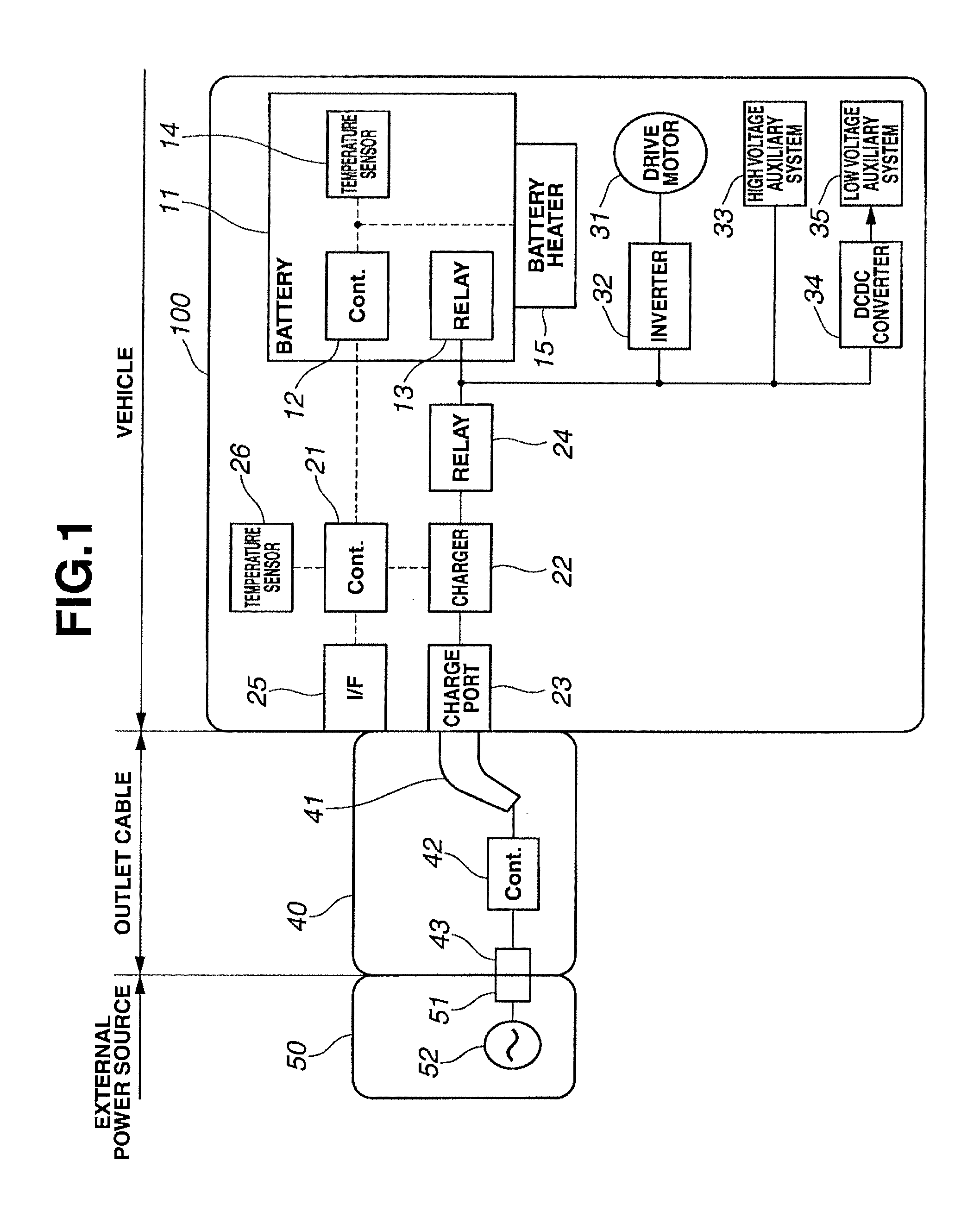
[0017]FIG. 1 is a general system diagram showing a charge control apparatus for a vehicle according to Embodiment 1. The vehicle to which Embodiment 1 is applied is an electric automobile that can travel using a battery as a sole energy source. Electric vehicle 100 includes electrically chargeable / dischargeable battery 11, and can be driven by converting a direct current power stored in battery 11 into an alternating current power through inverter 32 and supplying the converted power to drive motor 31. Battery 11 is charged by receiving electric power of external power source 50 through outlet cable 40 that connects external power source 50 and electric vehicle 100 with each other. Generally, examples of external power source 50 may include a commercial power source that is used in the case of ordinary charge, and a boost charger that is used in the case of boost charge. FIG. 1 shows the case of ordinary charge. Commercial power source 52 is generally supplied with current through p...

embodiment 2

[0043]Next, Embodiment 2 is explained. The basic construction is the same as that of Embodiment 1, and therefore, only structural features that are different from those of Embodiment 1 are explained. FIG. 5 is a flow chart showing a timer charge control processing that is executed in a charge control apparatus according to Embodiment 2. Although in Embodiment 1, it is judged whether or not the timer charge start time is advanced on the basis of operation / nonoperation of battery heater 15, Embodiment 2 differs from Embodiment 1 in that it is judged whether or not the timer charge start time is advanced on the basis of battery temperature.

[0044]In step S1, it is judged whether or not reservation of a timer charge time zone is made. If it is judged that reservation of the timer charge time zone is not made, the logic flow is ended. If it is judged that reservation of the timer charge time zone is made, the logic flow proceeds to step S2.

[0045]In step S2, an amount of shortage of charge...

embodiment 3

[0056]Next, Embodiment 3 is explained. The basic construction is the same as that of Embodiment 1, and therefore, only structural features that are different from those of Embodiment 1 are explained. FIG. 7 is a flow chart showing a timer charge control processing that is executed in a charge control apparatus according to Embodiment 3. Although in Embodiments 1 and 2, the required amount of extension of a charge time period by which the timer charge start time is advanced is set on the basis of the case where battery heater 15 is continuously operated during charge of battery 11. That is, the time advanced by the required amount of extension of a charge time period is identical with the time for checking the battery heater operating state and the battery temperature. In contrast, Embodiment 3 differs from Embodiments 1 and 2 in that the operating state of battery heater 15 is predicted with high accuracy and the required amount of extension of a charge time period is computed on th...


PUM

PropertyMeasurementUnit
electricallyaaaaaaaaaa
temperatureaaaaaaaaaa
electric poweraaaaaaaaaa

Abstract

When completion of timer charge before elapse of a designated time is designated by a timer charge reservation means for allowing a user to designate a predetermined charge time zone and a target amount of electric power to be charged to the battery, a timer charge start time is determined. Upon carrying out the timer charge, when it is predicted that the timer charge and battery heating are simultaneously carried out, a required amount of extension of a charge time period is determined so as to complete charge of the battery by the designated time, and starts charge of the battery at a time advanced relative to the timer charge start time by the required amount of extension of a charge time period. With this control, charge of the battery can be completed at a predetermined time without unnecessary enhancement in a required capacity of a battery heater.

Description

TECHNICAL FIELD[0001]The present invention relates to a charge control apparatus for a vehicle capable of travelling using electric power of a battery.BACKGROUND ART[0002]Patent Literature 1 discloses a technology of charge control of a battery in a vehicle capable of travelling using electric power of the battery. In the Patent Literature 1, when it is judged that charge of the battery cannot be completed within a predetermined time period due to a prolonged charge time period caused by a temperature drop of the battery, the battery is heated by a heater before a preset time for starting charge of the battery so as to complete charge of the battery in the predetermined time period.[0003]However, in order to complete heating of the battery before starting charge of the battery, it is necessary to heat the battery up to a predetermined temperature in a short period of time. In a case where a large-capacity battery useable as a power source for travel of the vehicle is heated, there o...

Claims


Application Information

Patent Timeline
Patent Type & Authority Applications(United States)
IPC IPC(8): H02J7/00H01M10/44H01M10/48H01M10/60H01M10/615H01M10/625H01M10/633H01M10/6571H02J7/04
CPCH02J7/0052H01M10/443H01M10/486H02J7/047H01M10/5016H01M10/502H01M10/5093H01M10/5006H01M10/625H01M10/63H01M10/615H01M10/66B60L1/02B60L2240/545B60L2240/80B60L2260/58Y02T10/7072Y02T90/14B60L50/51B60L58/12B60L58/27B60L53/18B60L53/62Y02T10/70Y02T90/12Y02E60/10H02J7/04H01M10/48H02J7/007192Y02T90/16H02J7/00
Inventor YAMAMOTO, NAOKIOKINO, KAZUHIKONIOKA, HISASHIHIGUCHI, SHINSUKEIMORI, TAKASHITAKANO, ATSUSHI
Owner NISSAN MOTOR CO LTD
Why Eureka
Try Eureka