Pressure sensing in implantable medical devices

Active Publication Date: 2005-04-07
MEDTRONIC INC
View PDF15 Cites 189 Cited by
  • Summary
  • Abstract
  • Description
  • Claims
  • Application Information

AI Technical Summary

Benefits of technology

[0010] The present invention can detect a malfunction in a catheter and take appropriate action if and when the malfunction occurs. By the sensing of pressure in the lumen of the catheter, cuts and leaks mig

Problems solved by technology

By the sensing of pressure in the lumen of the catheter, cuts and leaks might result in lower than normal pressure, the lack of appreciable p

Method used


Image

  • Pressure sensing in implantable medical devices
  • Pressure sensing in implantable medical devices
  • Pressure sensing in implantable medical devices

Examples


Embodiment Construction

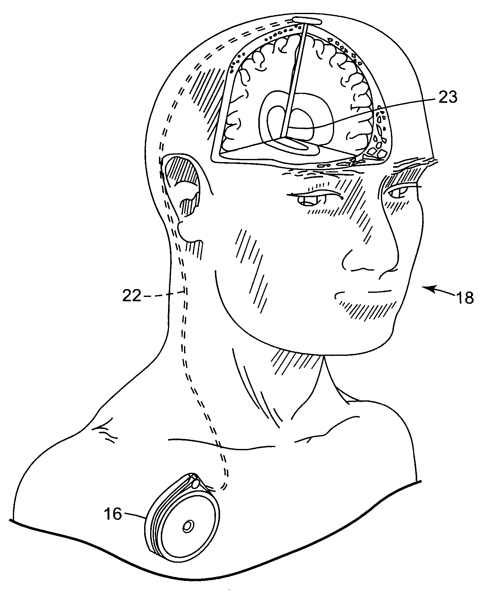
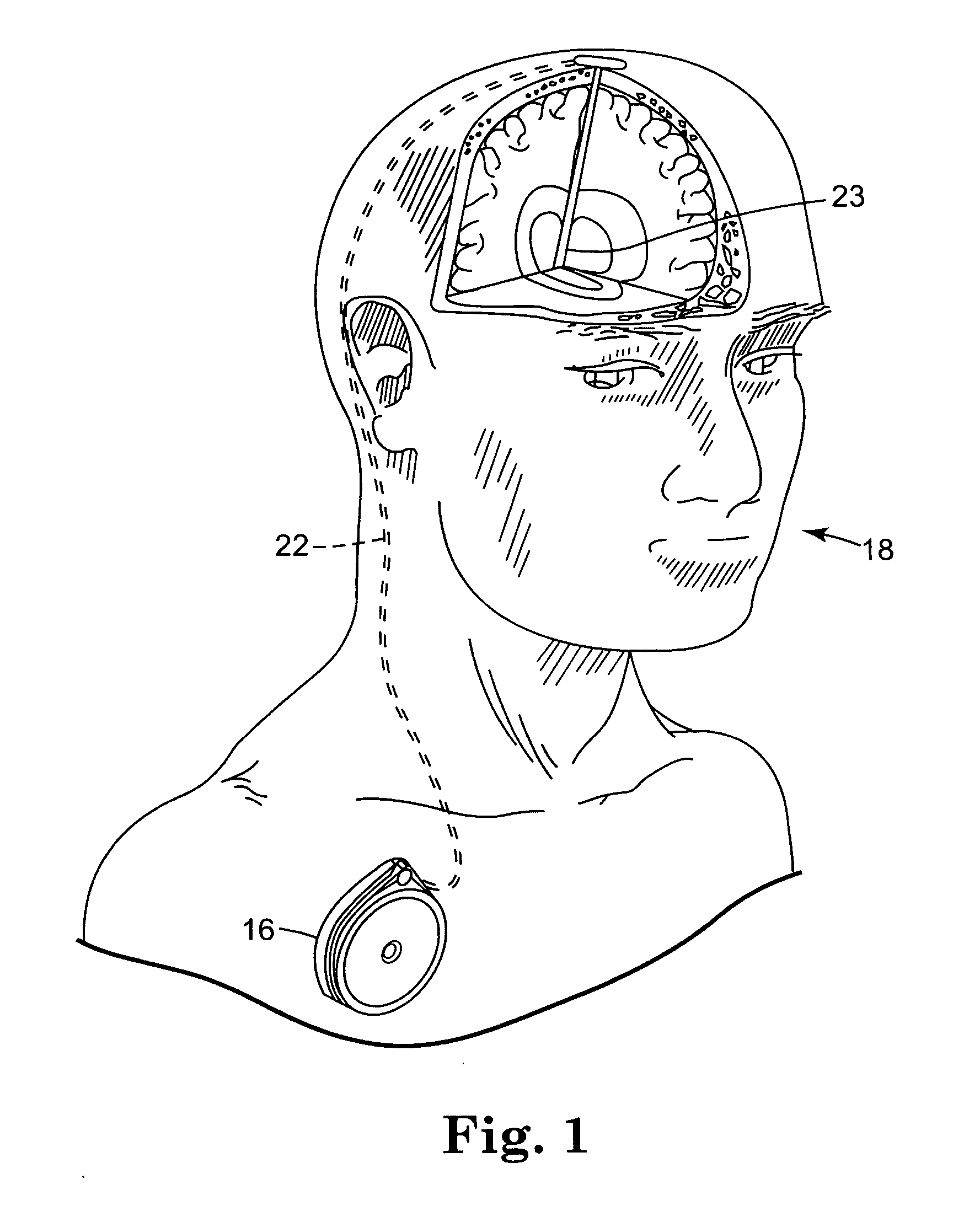
[0047]FIG. 1 shows implantable medical device 16, for example, a drug pump, implanted in patient 18. The implantable medical device 16 is typically implanted by a surgeon in a sterile surgical procedure performed under local, regional, or general anesthesia. Before implanting the medical device 16, a catheter 22 is typically implanted with the distal end position at a desired therapeutic delivery site 23 and the proximal end tunneled under the skin to the location where the medical device 16 is to be implanted. Catheter 22 may disgorge therapeutic substance at other than at its distal end. For example, catheter 22 may intentionally have a delivery region that is not proximate its distal, e.g., a hole or valve positioned somewhere before reaching the distal end of the catheter 22. Thus, catheter 22 may be placed in patient 18 with a delivery region of catheter 22 placed in or near to, generally proximate to, delivery site 23.

[0048] Implantable medical device 16 is generally implante...


PUM


Abstract

An implantable medical device for delivering a therapeutic substance to a delivery site in a patient. A reservoir holds a supply of the fluid therapeutic substance. A catheter has a proximal end, a delivery region and a lumen extending from the proximal end to the delivery region. The proximal end of the catheter is operatively coupled to the reservoir. The delivery region of the catheter is adapted to be placed proximate the delivery site in the patient. The therapeutic substance is adapted to be delivered through the lumen to the patient. A sensing device is operatively coupled with the lumen of the catheter being capable of detecting a pressure of the therapeutic substance in the lumen. A controller is operatively coupled to the sensing device, the controller being capable of taking an action in response to the pressure in the lumen.

Description

FIELD OF THE INVENTION [0001] The present invention relates generally to pressure sensing in implantable medical devices and, more particularly, to pressure sensing in implantable medical devices delivering a therapeutic substance to a patient. BACKGROUND OF THE INVENTION [0002] Implantable drug delivery or infusion devices and / or systems are commonly used, for example when chronic administration of a pharmaceutically active agent or therapeutic substance to a patient is required. An implantable infusion pump-catheter delivery system may be preferred when it is important to deliver the agent to a specific site or when the agent must be administered to spaced sites in tightly controlled, yet minute dosages. [0003] Typically, an implantable therapeutic substance delivery device has a reservoir for holding a supply of therapeutic substance awaiting delivery to a delivery site in the patient. A pump may be fluidly coupled to the reservoir for creating fluidic pressure to facilitate deli...

Claims


Application Information

Patent Timeline
IPC IPC(8): A61M5/142A61M5/168G01L9/00
CPCA61M5/14276A61M2205/3523A61M2205/3355A61M5/16854
Inventor MIESEL, KEITH A.
Owner MEDTRONIC INC
Why Eureka
Try Eureka