Noise attenuating device for a heating-ventilation-cooling system of a motor vehicle

a technology of noise attenuating device and motor vehicle, which is applied in the direction of ventilation system, heating type, domestic cooling apparatus, etc., can solve the problems of noise, noise can be bothersome for customers, and air flowing around these bends, etc., to reduce impingement or flow noise, reduce turbulence, and reduce noise. , the effect of reducing the noise of impingement or flow

Inactive Publication Date: 2005-04-14
FORD GLOBAL TECH LLC
View PDF15 Cites 47 Cited by
  • Summary
  • Abstract
  • Description
  • Claims
  • Application Information

AI Technical Summary

Benefits of technology

[0007] Another advantage of the present invention is that it can reduce impingement or flow noise generated by flow turbulence contacting a discontinuity in the duct system. Thus, it can

Problems solved by technology

The inventors herein have recognized a disadvantage with prior art noise reduction systems for climate control systems of passenger vehicles.
Air flowing around these bends, or through other discontinuities, can produce noise due to turbulent air

Method used


Image

  • Noise attenuating device for a heating-ventilation-cooling system of a motor vehicle
  • Noise attenuating device for a heating-ventilation-cooling system of a motor vehicle
  • Noise attenuating device for a heating-ventilation-cooling system of a motor vehicle

Examples


second embodiment

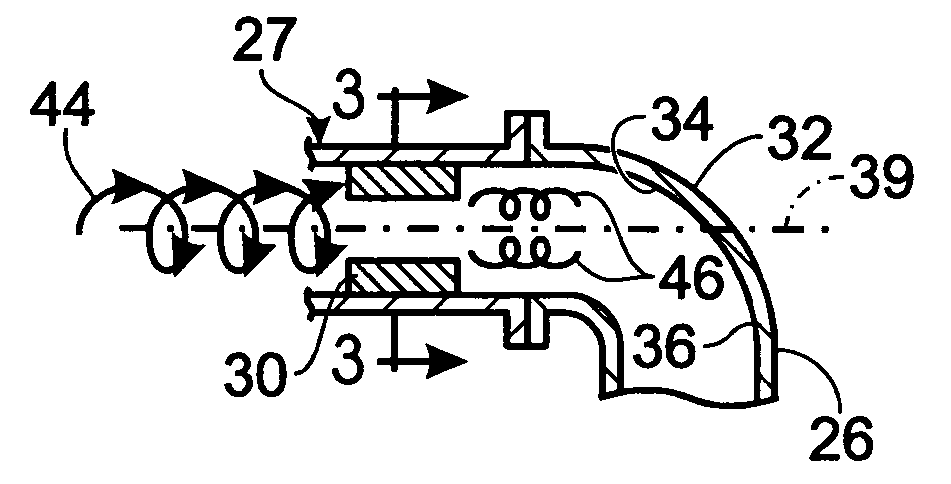
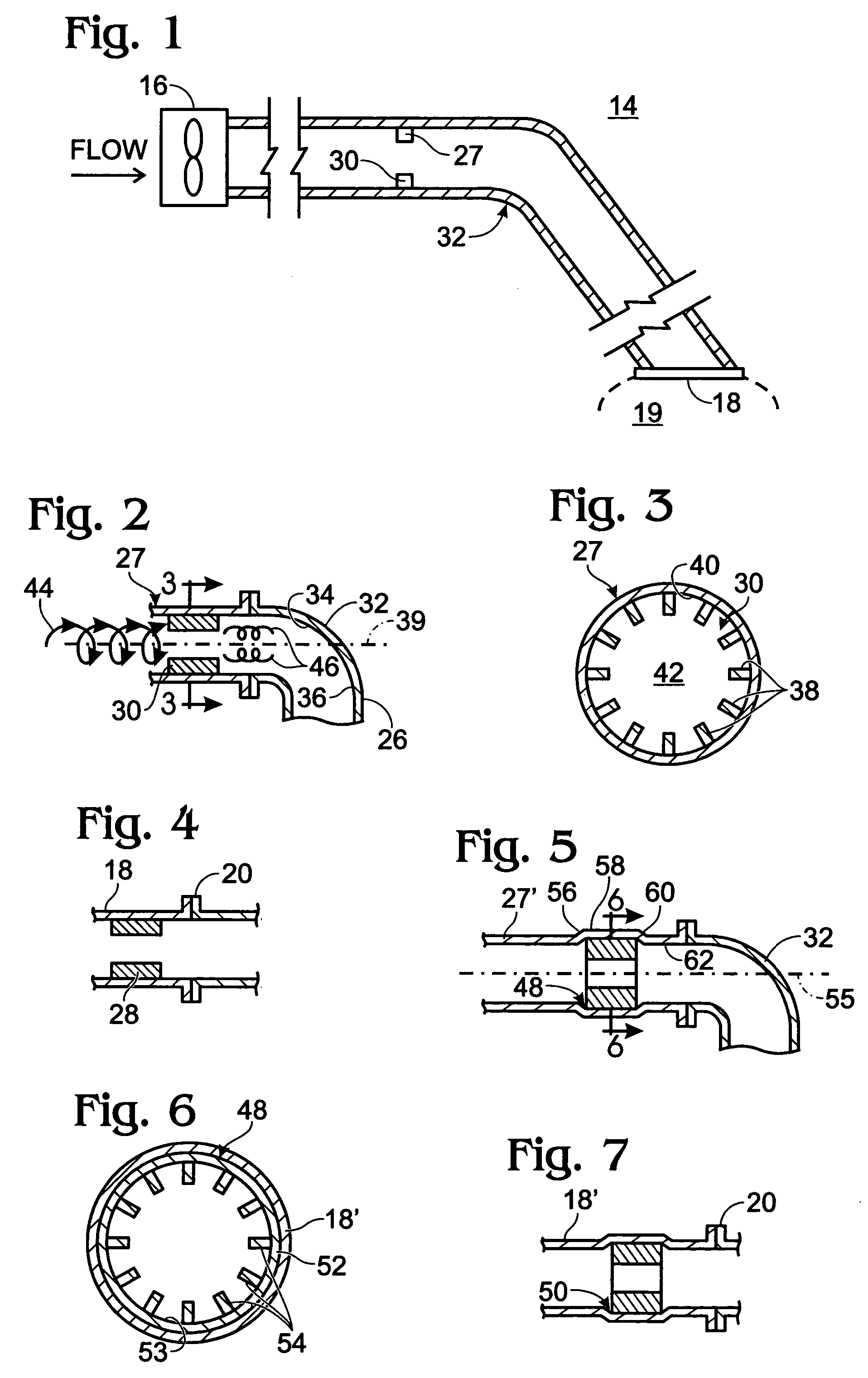
[0035] Referring to FIGS. 5 and 7, the present invention is shown in noise attenuation devices 48, 50. A difference between devices 48, 50 and device 30 is that devices 48, 50 are separate components that can be affixed within system 14 instead of being formed integral within duct sections of HVAC system 14. Referring to FIG. 5, device 48 may be utilized to reduce turbulence in exhaust gases upstream of bend 32 to reduce the noise, such as impingement noise, generated by gases contacting bend 32. Similarly, referring to FIG. 7, device 50 may be utilized to reduce turbulence in gases upstream of connection 20 to reduce noise, such as impingement noise, generated by gases passing through connection 20.

[0036] Referring to FIGS. 5 and 6, device 48 may include a tubular wall 52 and a plurality of vanes 52 extending inwardly from wall 52 a predetermined distance into an aperture 53. Further, vanes 54 may extend from a predetermined axial position on axis 55 a predetermined axial distance....

third embodiment

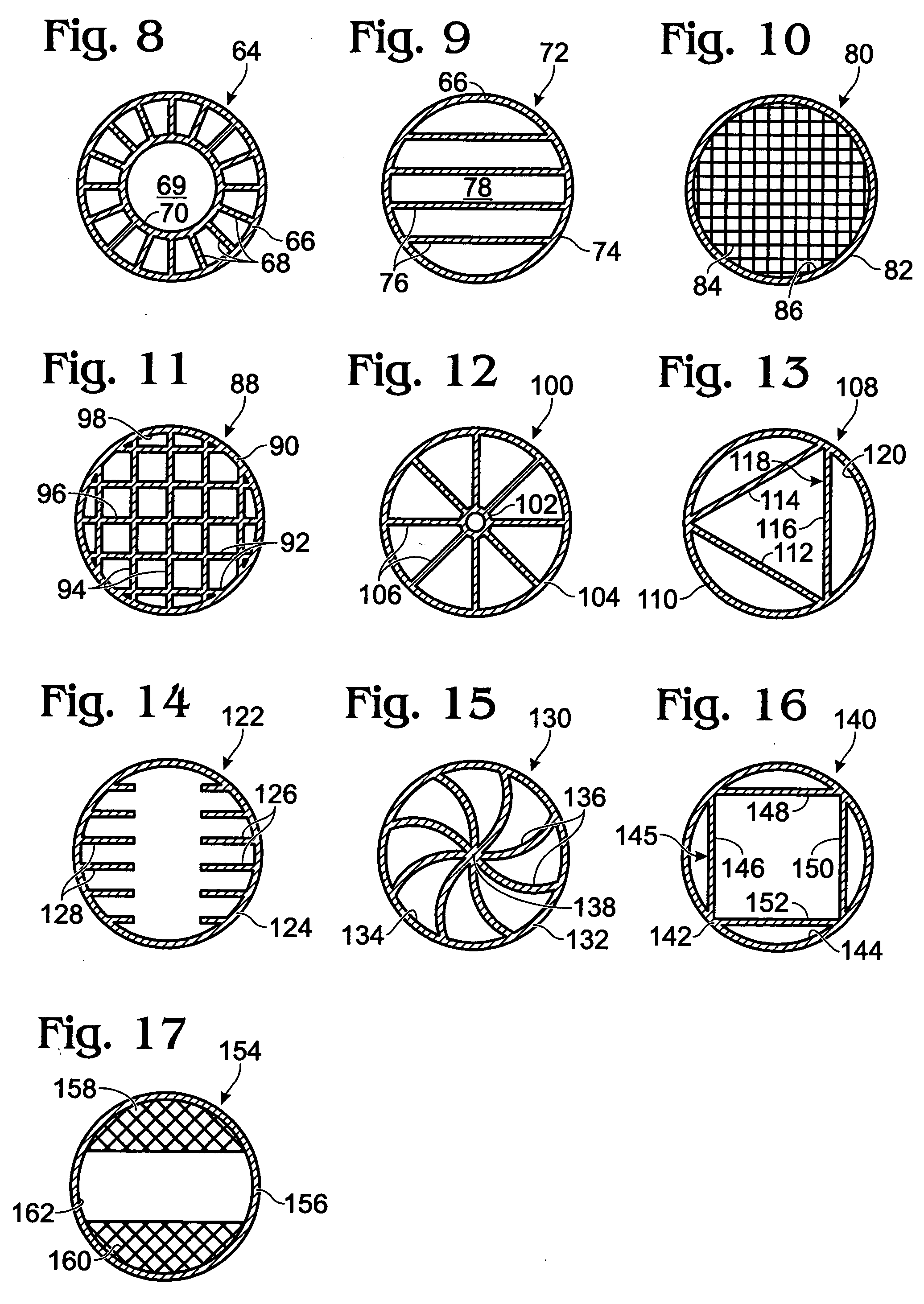
[0040] Referring to FIG. 8, a cross-sectional view of the present invention is shown as noise attenuation device 64. Device 64 may be disposed upstream of a discontinuity in system 14 to reduce noise, such as impingement or flow noise. As shown, device 64 may include a tubular wall 66 and a plurality of vanes 68 extending radially inwardly from wall 66 into an aperture 69 defined by wall 66. Further, vanes 68 may extend inwardly a predetermined distance and be affixed to an internal ring 70. Further, wall 66, vanes 68, and ring 70 may extend from a predetermined axial position a predetermined axial distance. Device 64 may be press-fit within system 14 as described above with respect to devices 48, 50. In an alternate embodiment (not shown), vanes 68 could be formed integrally within an duct section instead of being attached to wall 66.

fourth embodiment

[0041] Referring to FIG. 9, a cross-sectional view of the present invention is shown as noise attenuation device 72. Device 72 may be disposed upstream of a discontinuity in system 14 to reduce noise, such as impingement or flow noise. As shown, device 72 may include a tubular wall 74 having a plurality of vanes 76 extending across an aperture 78 defined by wall 74. Further, vanes 76 may be disposed parallel to one another across aperture 78. Device 72 may be press-fit within system 14 as described above with respect to devices 48, 50. In an alternate embodiment (not shown), vanes 78 could be directly integrally formed within a duct section instead of being attached to tubular wall 74.


PUM


Abstract

A system and method for reducing noise in an automotive heating, ventilation, and cooling system is described. A noise attenuation device using radial vanes upstream of a flow discontinuity, such as a bend in the ducting, and downstream of a blower fan is used to reduce noise.

Description

FIELD OF THE INVENTION [0001] The field of the invention relates to reducing noise caused by turbulent air flow in a climate control system of a passenger vehicle traveling on the road. BACKGROUND AND SUMMARY OF THE INVENTION [0002] Various methods have been applied to reduce noise in air ducts of a passenger vehicle. One approach attempts to improve the grill on an instrument panel of the vehicle, as described in U.S. Pat. No. 4,957,036. [0003] The inventors herein have recognized a disadvantage with prior art noise reduction systems for climate control systems of passenger vehicles. Specifically, such system can have duct systems with significant amounts of bending, or other discontinuities, so that the system can be packaged into the vehicle. This is especially true with more modern vehicle designs where space outside the passenger compartment is at a premium. Air flowing around these bends, or through other discontinuities, can produce noise due to turbulent air flow caused by a...

Claims


Application Information

Patent Timeline
IPC IPC(8): B60H1/00E04F17/04F01N1/08F24F13/08
CPCB60H1/00564B60H2001/006F24F2013/088F01N1/08F01N1/086E04F17/04
Inventor CHOI, MICHAEL
Owner FORD GLOBAL TECH LLC
Why Eureka
Try Eureka