Suspension control system and suspension control method for vehicle

a suspension control system and suspension control technology, applied in the direction of resilient suspensions, interconnection systems, vehicle components, etc., can solve the problems of driver discomfort during riding, unstable steering during vehicle travel around the corner, etc., to achieve ride comfort and stability during travel

Inactive Publication Date: 2005-04-14
AISIN AW CO LTD
View PDF5 Cites 24 Cited by
  • Summary
  • Abstract
  • Description
  • Claims
  • Application Information

AI Technical Summary

Benefits of technology

Accordingly, a good ride sensation (riding comfort of the passengers) and good steering stability during the running of the vehicle can be maintained even when there are irregularities in the road surface approaching and / or in the corner.
Accordingly, riding comfort and stability during travel can be maintained in a preferred manner even when the road surface state approaching the corner and the road surface within the corner are slippery.

Problems solved by technology

However, in the suspension control system of JP-A-9-114367, the corner information obtained from the navigation device includes no information relative to the state of the road surface at the corner.
Accordingly, for example, when the road surface at the corner is irregular and / or slippery, steering during travel of the vehicle around the corner may become unstable and the driver may feel riding discomfort (an unpleasant sensation).

Method used


Image

  • Suspension control system and suspension control method for vehicle
  • Suspension control system and suspension control method for vehicle
  • Suspension control system and suspension control method for vehicle

Examples


first embodiment

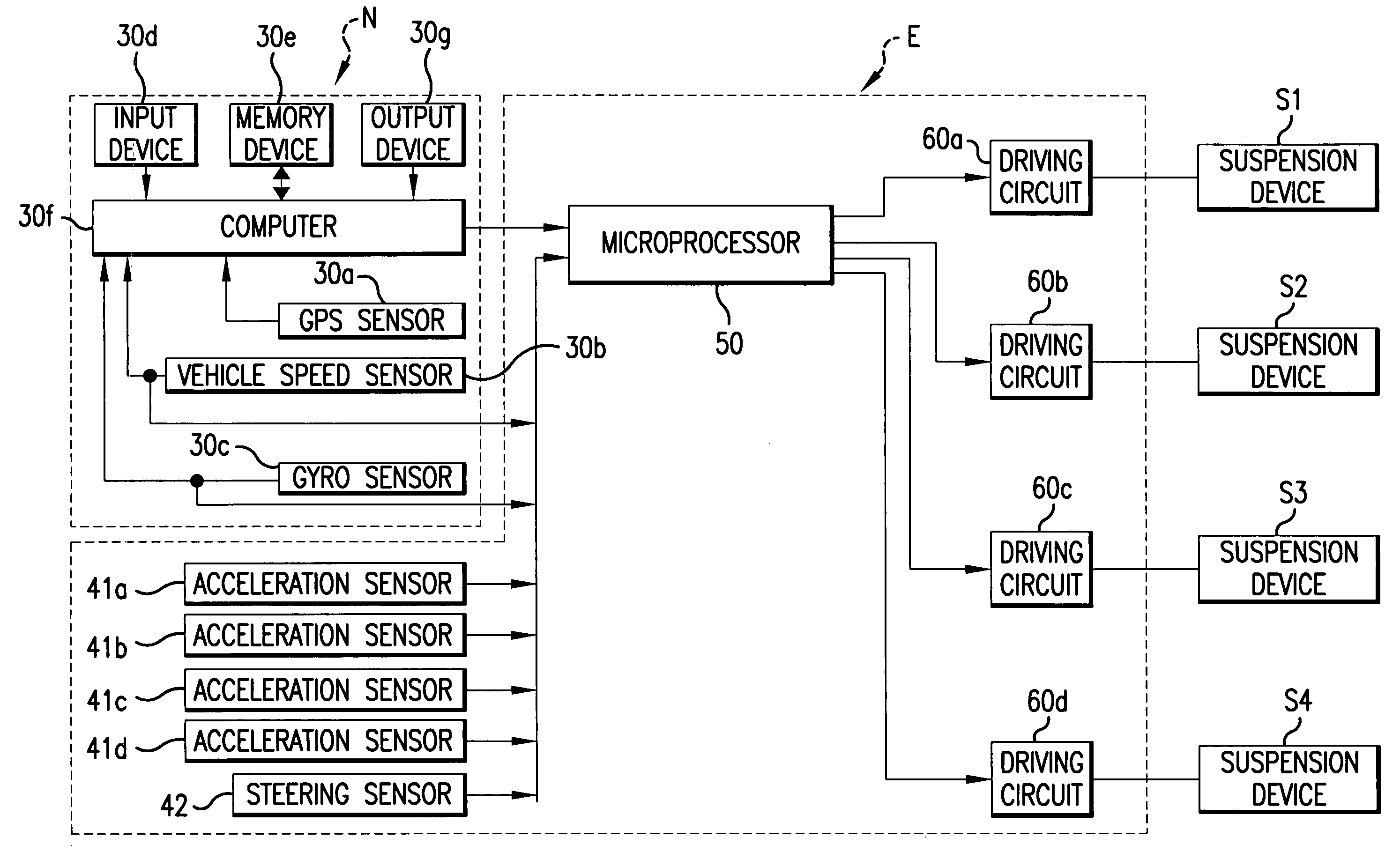
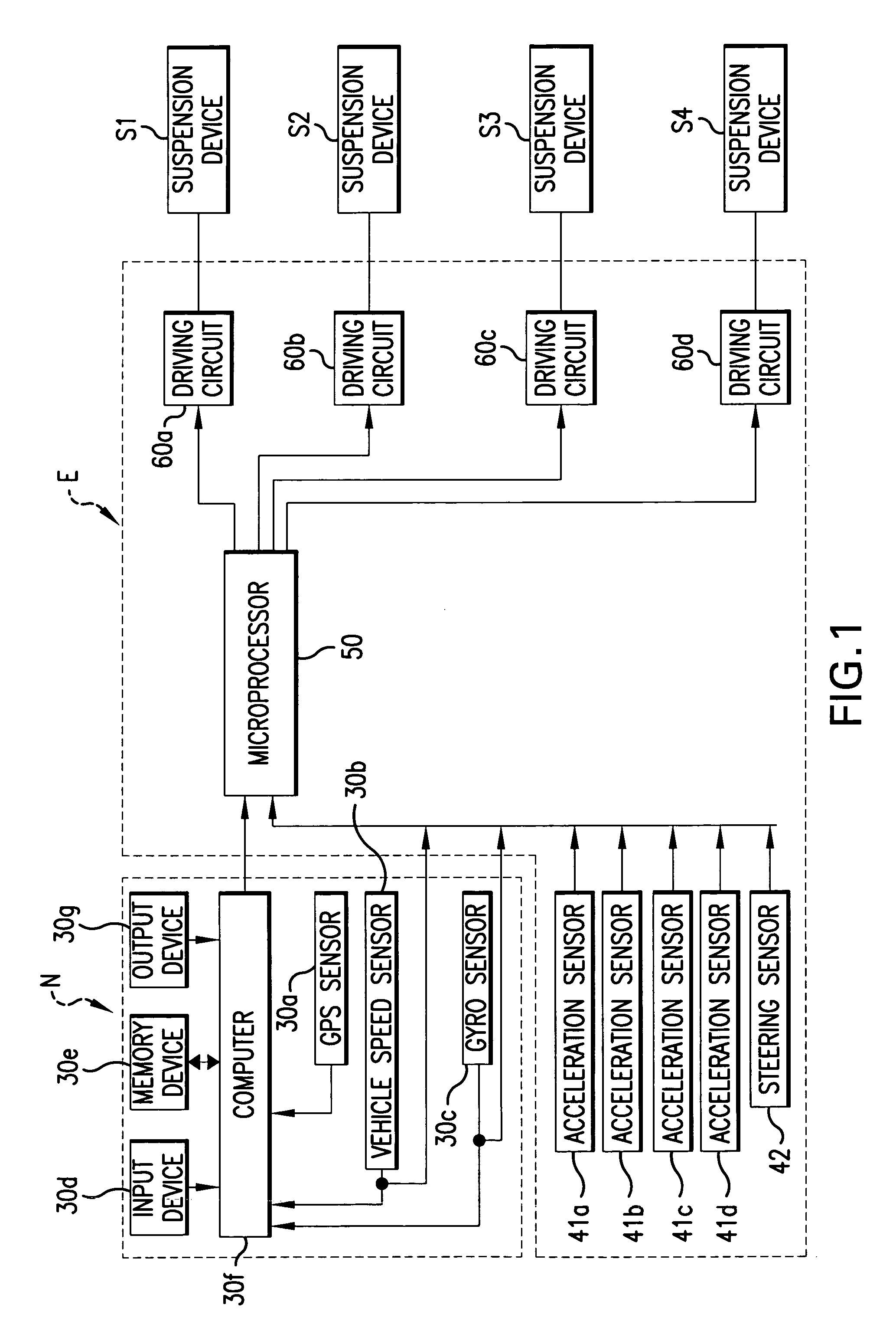
FIG. 1 shows a first embodiment of a suspension control system of the present invention, designed for a sedan type automobile and including suspension devices S1 to S4 and an electronic controller E.

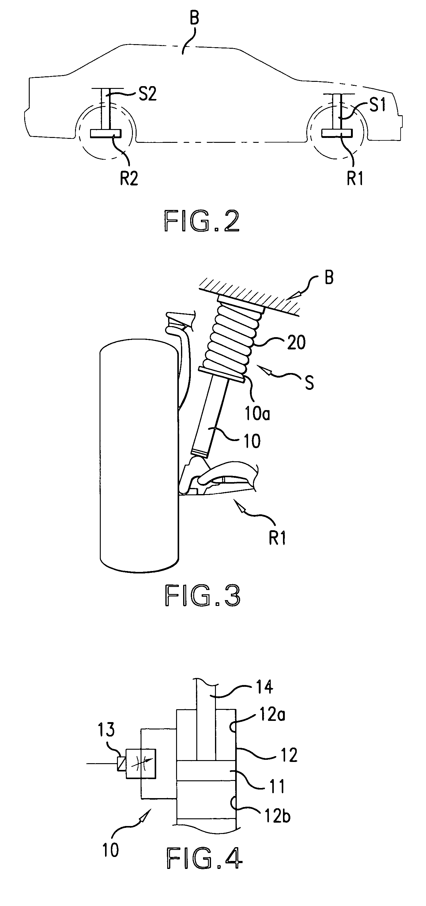
As shown in FIG. 2, the suspension device S1 is interposed and mounted between a wheel support element R1 supporting the right-hand side front wheel of the automobile, and the right-hand side front portion of the vehicle frame B.

As shown in FIG. 3, this suspension device S1 has a damper 10 and a coil spring 20. The lower end portion of damper 10 is supported on the wheel support element. The wheel support element, to which the lower end of the shock absorber attaches, may be different for front and rear wheels and for different vehicles, e.g., axle housing, lower suspension arm, steering knuckle, bearing housing or motor housing. The coil spring 20 is coaxially mounted on the damper 10, external thereto, between a flange 10a arranged in an axially intermediate location on the damper ...

second embodiment

FIG. 16 shows a second embodiment of the present invention in which rotational speed sensors 43a, 43b are used instead of the acceleration sensors 41a to 41d in the electronic controller E of the above first embodiment. Each of these rotational speed sensors 43a, 43b is arranged near a drive wheel of an axle of the automobile. Each of these rotational speed sensors 43a, 43b detects the rotational speed of a drive wheel.

Further, this second embodiment is operated in accordance with the flow chart of FIG. 17, instead of the flow chart of FIG. 8 as in the first embodiment. Further, this second embodiment employs the slip degree setting routine 130a of FIG. 18 and the damping level determination routine 140a of FIG. 19, instead of the degree of irregularity setting routine 130 of FIG. 9 and the damping level determination routine 140 of FIG. 10 in the suspension control program of the first embodiment. Other features are similar to those of the first embodiment.

In this second embodi...


PUM


Abstract

A suspension control system and a suspension control method for a vehicle control the suspension based on the condition of the road surface traveled by the vehicle in addition to information pertaining to a corner obtained from a navigation device when the vehicle approaches the corner. A microprocessor controls damping forces of suspension devices on the basis of a degree of irregularity of the road surface detected immediately preceding entry of the automobile into a turn around the corner, and corner information from the navigation device.

Description

CROSS-REFERENCE TO RELATED APPLICATION This application claims, under 35 USC 119, priority of Japanese Patent Application No.2003-336127 filed on Sep. 26, 2003, the teachings of which are incorporated by reference herein, in their entirety, including the specification, drawings and abstract. Copending application U.S. Ser. No. 10 / ______ (Attorney Docket No. AW-C462) in the name of Fumiharu OGAWA as inventor, entitled “VEHICLE SUSPENSION CONTROL SYSTEM AND SUSPENSION CONTROL METHOD” and filed on even date herewith discloses and claims related subject matter. BACKGROUND OF THE INVENTION 1. Field of the Invention The present invention relates to a suspension control system and to a suspension control method for a vehicle. 2. Description of the Related Art JP-A-9-114367 discloses a suspension control system in which the suspension is adjusted in advance, for example, just before the vehicle starts to turn a corner in traveling a predetermined route, on the basis of the speed of the...

Claims


Application Information

Patent Timeline
Patent Type & Authority Applications(United States)
IPC IPC(8): B60G17/08B60G17/015G08G1/16
CPCB60G17/08B60G2400/102B60G2400/41B60G2400/821B60G2800/916B60G2401/16B60G2500/10B60G2600/184B60G2800/162B60G2400/824
Inventor OGAWA, FUMIHARU
Owner AISIN AW CO LTD
Why Eureka
Try Eureka