Equipment fan

a technology of equipment fan and fan body, which is applied in the direction of electrical apparatus, electric motor control, dynamo-electric machines, etc., can solve the problems of difficult replacement of the fan, e.g. for a repair, and achieve the effect of quick replacement of any failing components

Inactive Publication Date: 2005-04-14
EBM PAPST ST GEORGEN & -
View PDF11 Cites 7 Cited by
  • Summary
  • Abstract
  • Description
  • Claims
  • Application Information

AI Technical Summary

Benefits of technology

[0003] It is therefore an object of the invention to provide a modular fan structure which facilitates quick replacement of any failing components.
[0004] According to the invention, this object is achieved by providing a housing containing non-wearing components, which releasably engages a replaceable module including an external rotor, fan wheel, a hub, an internal stator mounted on the hub, and at least one strut connecting the hub to a cylindrical casing. In a fan of this kind, the housing can be mounted on an object that is to be ventilated, since it usually contains only mechanical parts that are not subject to wear. The component having the fan wheel, external-rotor motor, and casing part, on the other hand, can easily be detached from said housing as necessary, and repaired or replaced with a new component of identical type. An exchange of this kind can be made in a very short period of time, so that damage due to failure of a fan does not result in extended downtime of the equipment being cooled by it.
[0005] Another manner of achieving the stated object is to equip the motor with at least one signal line, through which control signals can be fed from outside to the motor, and through which a fault signal can be fed back from the motor to the outside, so that something can be done about the fault state. It enables rapid fault detection, and thus efficient replacement of a defective fan once a fault has been detected.

Problems solved by technology

Equipment fans are often installed in inaccessible locations where subsequent replacement of the fan, e.g. for a repair, is very difficult.

Method used


Image

  • Equipment fan
  • Equipment fan
  • Equipment fan

Examples


Embodiment Construction

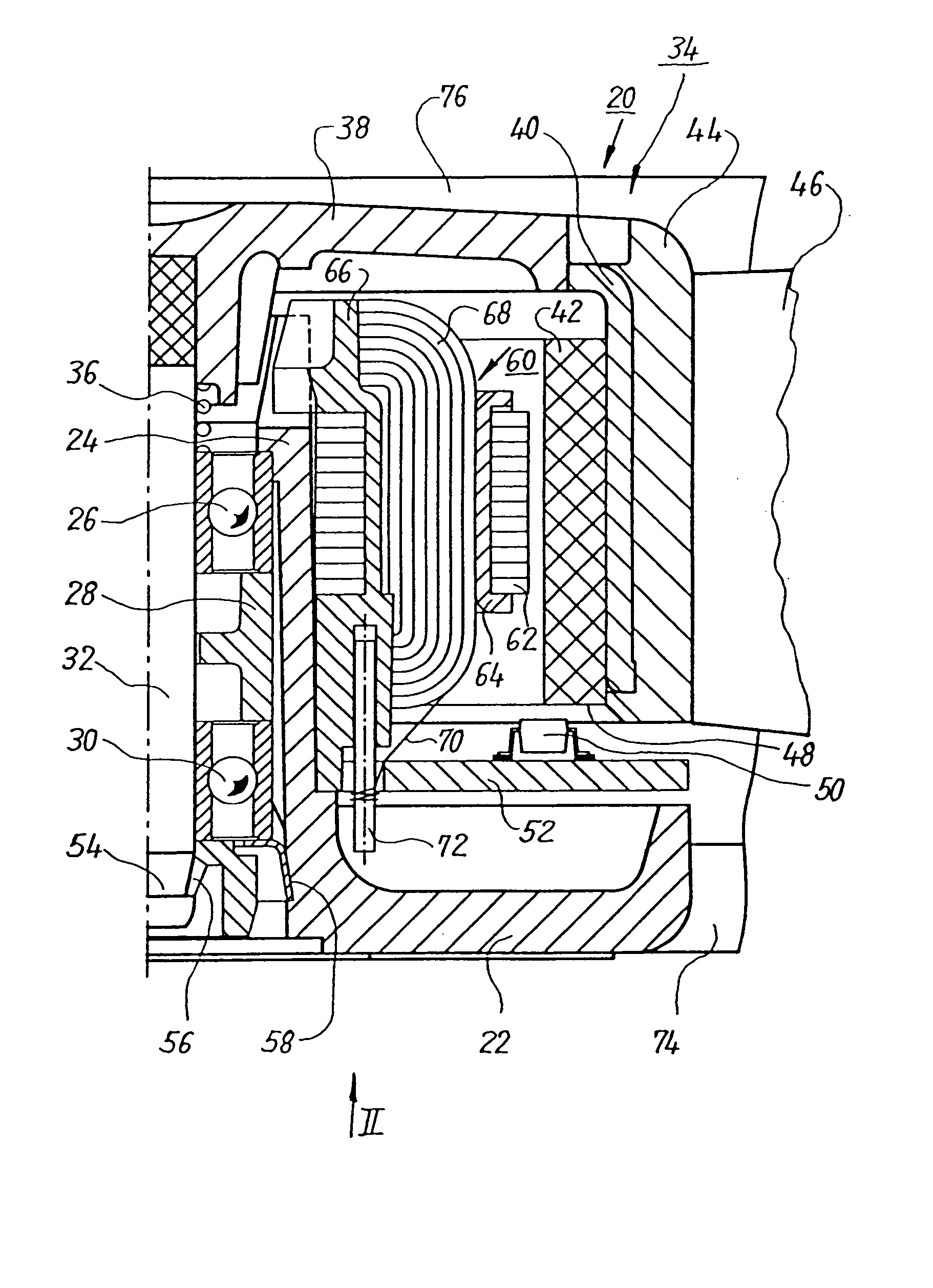
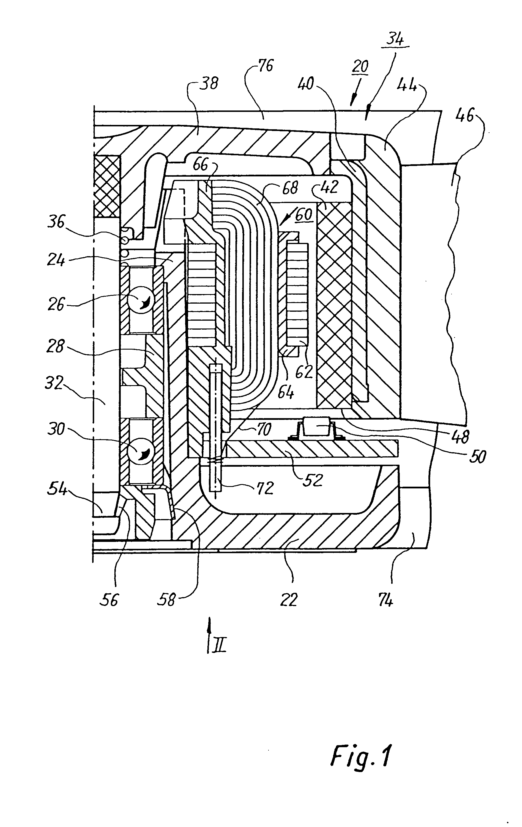
[0023]FIG. 1 shows a greatly magnified section through the right half of an external-rotor motor 20, the left half being essentially mirror-symmetrical thereto. To save drawing space, fan blade 46 and strut 74 are shown broken away. The motor has a hub 22, made of a suitable plastic, that is configured integrally with a bearing support tube 24 in which an upper ball bearing 26, a spacer 28 for the outer races, and a lower ball bearing 30 are arranged, which ball bearings support central shaft 32 of an external rotor 34. The inner races of ball bearings 26, 30 are braced against one another by a compression spring 36 that is arranged between the inner race of ball bearing 26 and a rotor part 38. The latter, as depicted, is mounted at the upper end of shaft 32 and carries a ferromagnetically soft ring 40 in which a rotor magnet 42 is arranged. Extending around ring 40 is an annular part 44 made of plastic, which is configured integrally with five fan blades 46. Opposite lower end 48 o...


PUM


Abstract

An improved fan useful for ventilating applications in motor vehicles features a modular structure, which facilitates quick replacement of any components likely to fail. A first module (110) is intended for permanent installation on the part that is to be cooled. A second module (110) is configured for quick engagement to and disengagement from the first module. The second module preferably comprises a hub (22; 362), an internal stator (60; 332) mounted on the hub, and one or more struts (74; 344) connecting the hub to a cylindrical casing part (76; 336) which surrounds but is spaced from the outside of the fan wheel (46; 348). The struts form a lattice (112) which can be easily grasped for swapping out the second module when repair or replacement becomes necessary. The fan has a Hall sensor (50) and a control circuit (156) which regulates fan speed according to PWM (Pulse Width Modulation) or DC voltage signals (164) supplied from outside and has means (186; 244) for generating a fault signal in the event of a fault state, and for sending the fault signal out on a control line (90).

Description

FIELD OF THE INVENTION [0001] The invention concerns, inter alia, an equipment fan having a fan wheel that is driven by an external-rotor motor whose internal stator is mounted on a hub. The invention preferably concerns a fan of this kind that can communicate with an external control device via a control line (“bus”). BACKGROUND [0002] Equipment fans are often installed in inaccessible locations where subsequent replacement of the fan, e.g. for a repair, is very difficult. This applies in particular to land and water vehicles and aircraft. SUMMARY OF THE INVENTION [0003] It is therefore an object of the invention to provide a modular fan structure which facilitates quick replacement of any failing components. [0004] According to the invention, this object is achieved by providing a housing containing non-wearing components, which releasably engages a replaceable module including an external rotor, fan wheel, a hub, an internal stator mounted on the hub, and at least one strut conne...

Claims


Application Information

Patent Timeline
Patent Type & Authority Applications(United States)
IPC IPC(8): F04D25/06F04D29/60
CPCF04D25/0613Y10S388/903F04D29/601
Inventor WINKLER, WOLFGANG ARNO
Owner EBM PAPST ST GEORGEN & -
Why Eureka
Try Eureka