Method and system for controlling motor torque

a technology of motor torque and control function, applied in the direction of motor/generator/converter stopper, dynamo-electric converter control, dc-ac conversion without reversal, etc., can solve the problems of failure of total system, failure of control function, saturation of current control output,

Active Publication Date: 2005-04-14
FUJI ELECTRIC CO LTD
View PDF5 Cites 30 Cited by
  • Summary
  • Abstract
  • Description
  • Claims
  • Application Information

AI Technical Summary

Benefits of technology

The foregoing and other objectives, features, and advantages of the invention will be apparent from the following, more particular,

Problems solved by technology

The output of the power converter 25 ceases supplying power, and in an apparatus in which continuous operation of the motor 27 is required, the overload condition inevitably results in total system failure.
However, the above-described solution has disadvantages, as using a predetermined limit value on the output voltage command value, as the current control output can become saturated when the power supply voltage falls.
In that condition, the maximum output value of the power converter falls below the maximum output specification, and because the output voltage command value then never reaches the predetermined limit, again causing saturation of the control function and failure of responsiveness of the system.
Although torque limitation during a drop in power supply voltage is possible, the effect of the voltage drop at the converted input that is caused by the input impedance is not considered.
Again, as in the case of the related art shown in FIG. 8, continuous operation of the motor is not guaranteed.

Method used


Image

  • Method and system for controlling motor torque
  • Method and system for controlling motor torque
  • Method and system for controlling motor torque

Examples


Embodiment Construction

The present invention provides a system and method for controlling motor torque that avoids the above-described disadvantages of the prior art.

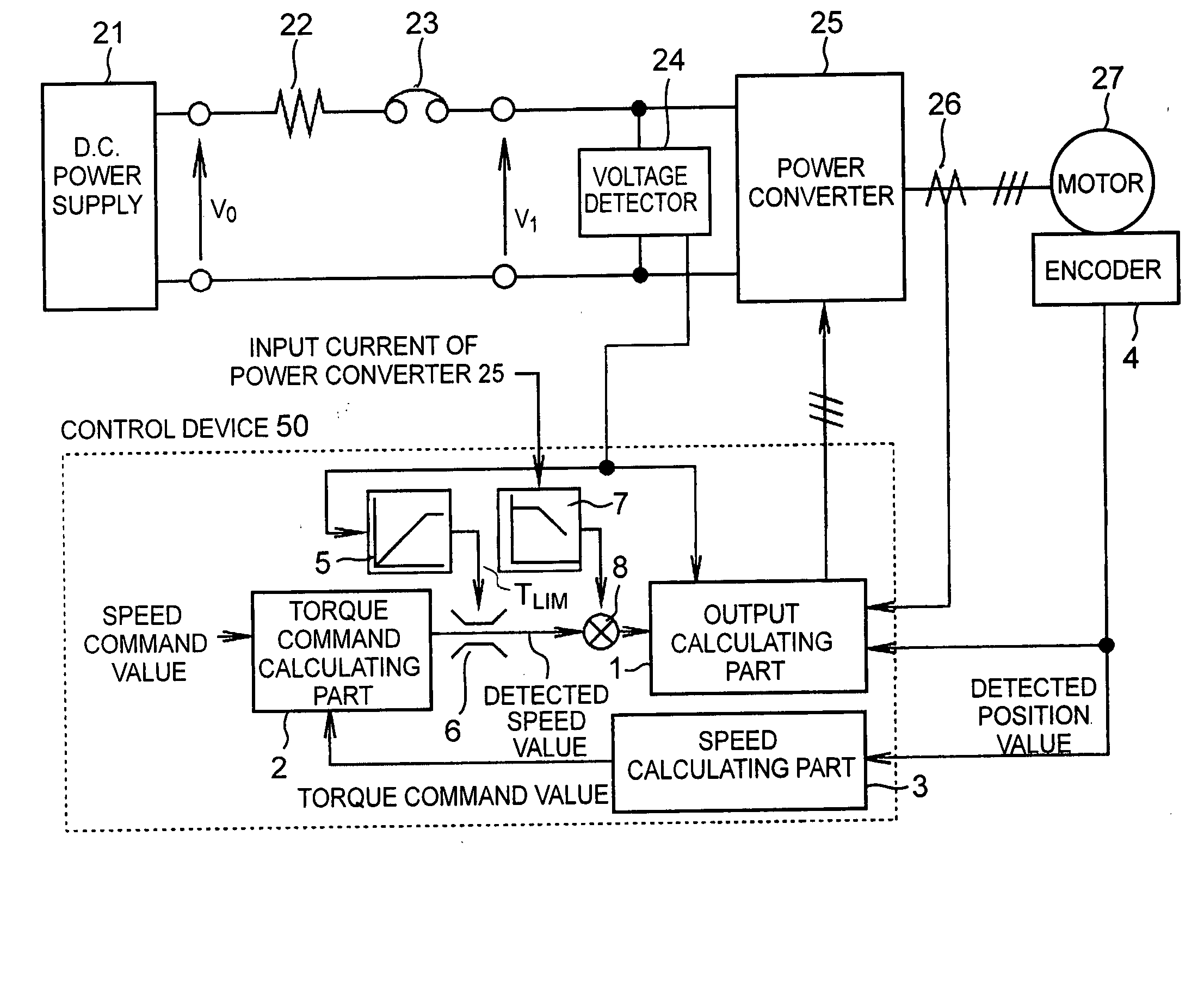
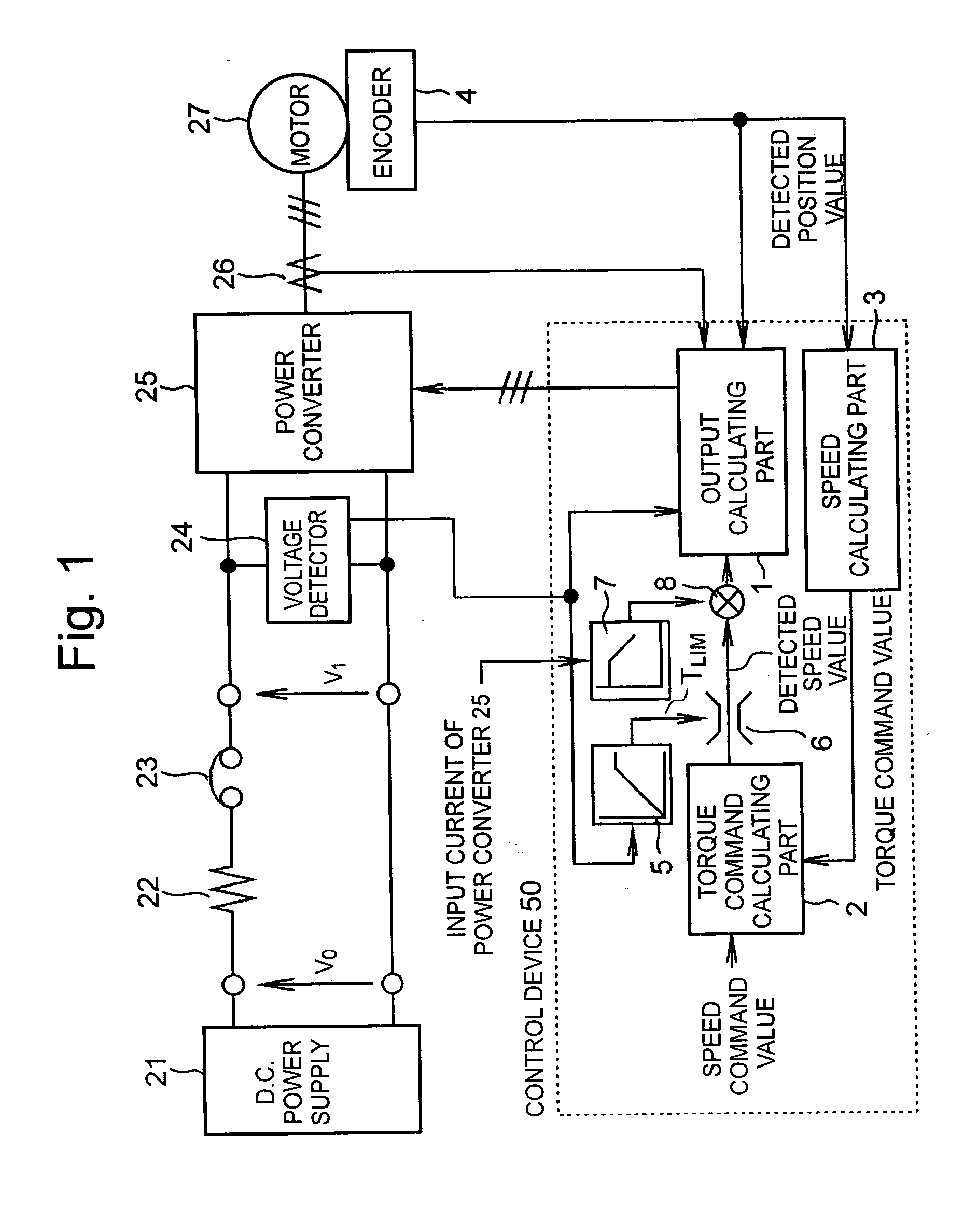
FIG. 1 depicts a system in accordance with an embodiment of the present invention that maintains a high responsiveness of torque control even when a power source voltage drop due to input impedance or a variation in power supply voltage occurs at the input of the system. In all of the depicted embodiments, constituent elements that are the same as those in FIG. 8 have been given the same reference numerals and the following description will center on the elements and functionality, which differ from those in FIG. 8.

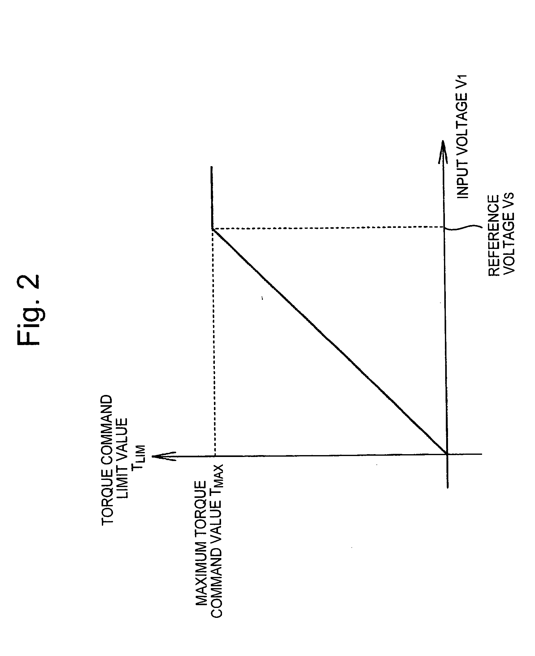
The input voltage at a power converter 25 that supplies power to motor 27 is detected via a voltage detector 24. A control device 50 provides for control of motor in conformity with the detected voltage, permitting control device 50 to set a limit on the commanded torque that avoids control function saturation problems by provi...


PUM


Abstract

A method and system for controlling motor torque provides improved responsiveness and reliability in motor control applications. The motor control system includes a power converter, a voltage detector for detecting the converter input voltage and a control circuit for controlling the converter. The control circuit includes a torque command limit value generator and a torque command limiter for limiting a torque command value. The system may also include a torque command coefficient generator for generating a coefficient corresponding to an input current of the power converter, and a multiplier for calculating a final torque command value for the motor by multiplying together the torque command value and the torque command coefficient. The torque command limit and coefficient values may be determined from the converter input voltage, calculated or detected converter input current and calculated input impedance between a power supply and the converter.

Description

BACKGROUND OF THE INVENTION 1. Field of the Invention The present invention relates generally motor control systems, and more specifically to motor control system that controls positioning motor torque. 2. Background of the Invention Motor control systems are used in many applications, including industrial and consumer applications. The control of a motor's position, velocity and / or acceleration is the object of a motor control system, which attempts to position or control the speed of the motor at a commanded rotation, location and / or velocity. FIG. 8 shows a motor drive control system as is known in the related art. The apparatus includes a power converter 25 such as an inverter for driving a 3-phase alternating-current (AC) motor 27, having a direct-current (DC) power supply 21 as an input, and a control device 100 for controlling the system. Power converter 25 converts DC power from DC power supply 21 into AC power and supplies it to motor 27. A circuit breaker 23 interrupt...

Claims


Application Information

Patent Timeline
Patent Type & Authority Applications(United States)
IPC IPC(8): H02P6/08H02P6/06H02P6/28
CPCH02M7/48Y10S388/903H02P23/004H02P6/08H02P23/30
Inventor NAGAKURA, TAKAYUKI
Owner FUJI ELECTRIC CO LTD
Why Eureka
Try Eureka