Optical pick-up device

a technology of optical pick-up and optical lens, which is applied in the direction of data recording, instruments, disposition/mounting of heads, etc., can solve the problems of increasing the size deteriorating the efficiency of recording or reproducing information, and a large amount of information, so as to prevent an increase in the size and manufacturing cost of the optical pick-up device, and suppress the variation of the inclination angle of the object lens

Inactive Publication Date: 2005-04-14
TEAC CORP
View PDF5 Cites 13 Cited by
  • Summary
  • Abstract
  • Description
  • Claims
  • Application Information

AI Technical Summary

Benefits of technology

Accordingly, the present invention is designed to solve the above-mentioned problems, and it is an object of the present invention to provide an optical pick-up device capable of suppressing the inclination of a lens actuator in the jitter direction caused by the variation of the ambient temperature thereof so as to stably record or reproduce information to or from an optical disk.
According to the present invention described in claim 1, the suspension holder is formed of a plurality of members having different coefficients of linear expansion, and the members having a higher coefficient of linear expansion are arranged on the rear side of the suspension holder. Therefore, when the ambient temperature of the actuator assembly increases due to the heat generated from a semiconductor laser element, an LSI of an optical disk drive or the like, the members having a higher coefficient of linear expansion that constitute the suspension holder are more largely expanded in the jitter direction than the other members having a lower coefficient of linear expansion. Accordingly, the members having a higher coefficient of linear expansion can press the supporting member fixed to the rear side of the suspension holder in the jitter direction to correct the inclination of the lens actuator in the jitter direction. As a result, it is possible to suppress a variation in the inclination angle of the object lens, and thus to stably record or reproduce information to or from an optical disk.
Further, according to the present invention described in claim 2, the first member for fixing the suspension holder to the yoke base and the second member that has a coefficient of linear expansion higher than that of the first member and abuts on the supporting member are integrated into one body. Therefore, it is possible to allow the suspension holder to function as a mechanism for correcting a tilt in the jitter direction. In other words, since it is not necessary to additionally provide a servomechanism for correcting a tilt in the jitter direction, it is possible to prevent an increase in the size and manufacturing costs of the optical pick-up device.
Furthermore, according to the present invention described in claim 3, the second member is arranged on the upper side of the abutting portion of the first member abutting on the supporting member. Therefore, since the second member having a coefficient of linear expansion higher than that of the first member presses an upper half portion of the supporting member in the jitter direction, it is possible to more effectively correct the inclination of the lens actuator.
Moreover, according to the present invention described in claim 4, the first member is made of a liquid crystal polymer, and the second member is made of polyamide resin. Therefore, it is possible to optimize conditions necessary for correcting the inclination of the lens actuator, such as coefficients of linear expansion.

Problems solved by technology

As a result, the recording efficiency or reproducing efficiency of information deteriorates.
That is, a separate control system for controlling the inclination in the jitter direction must be constructed, which results in an increase in the size of the optical pick-up device and a complexity of structure thereof.

Method used


Image

  • Optical pick-up device
  • Optical pick-up device
  • Optical pick-up device

Examples


Embodiment Construction

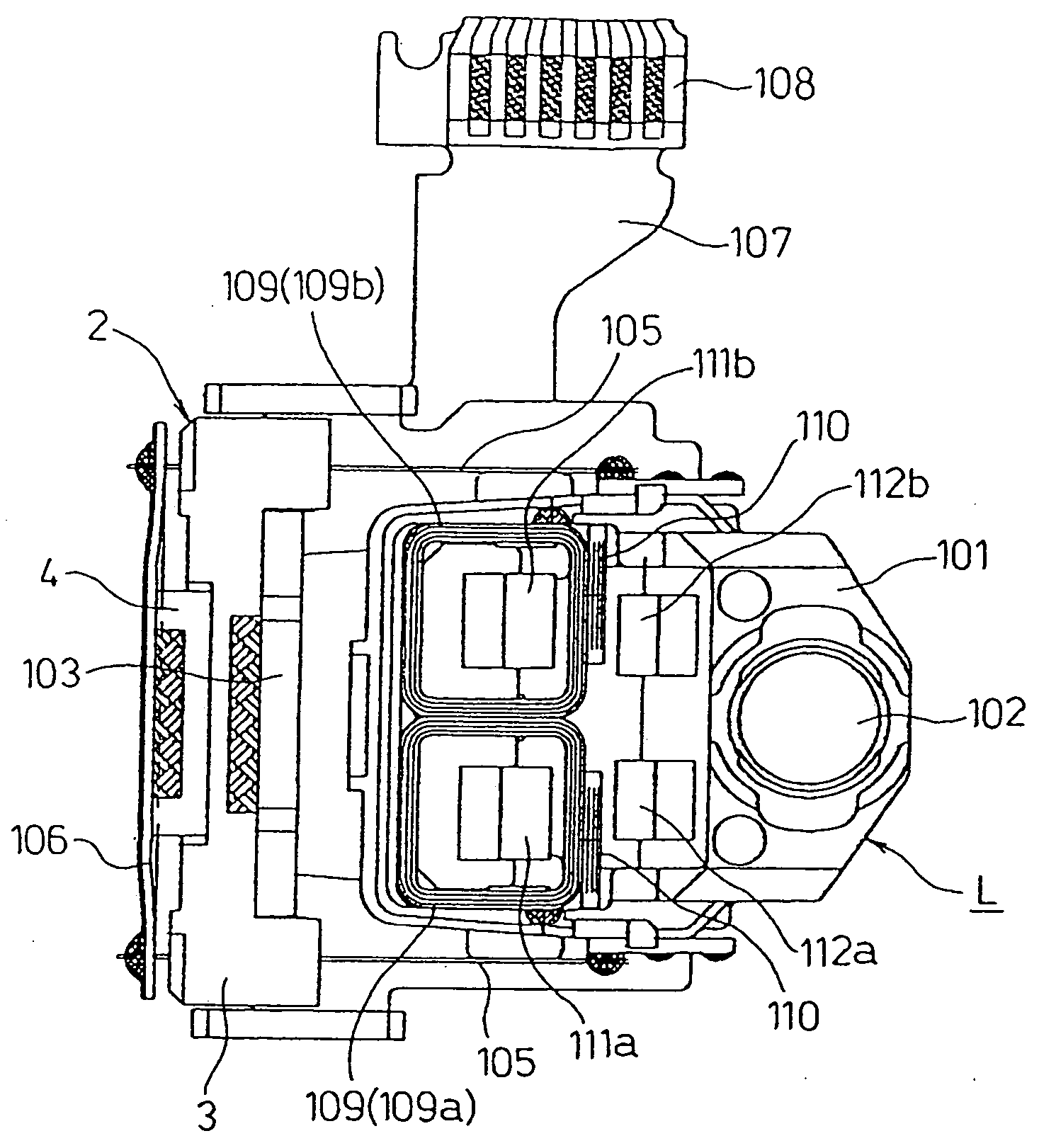
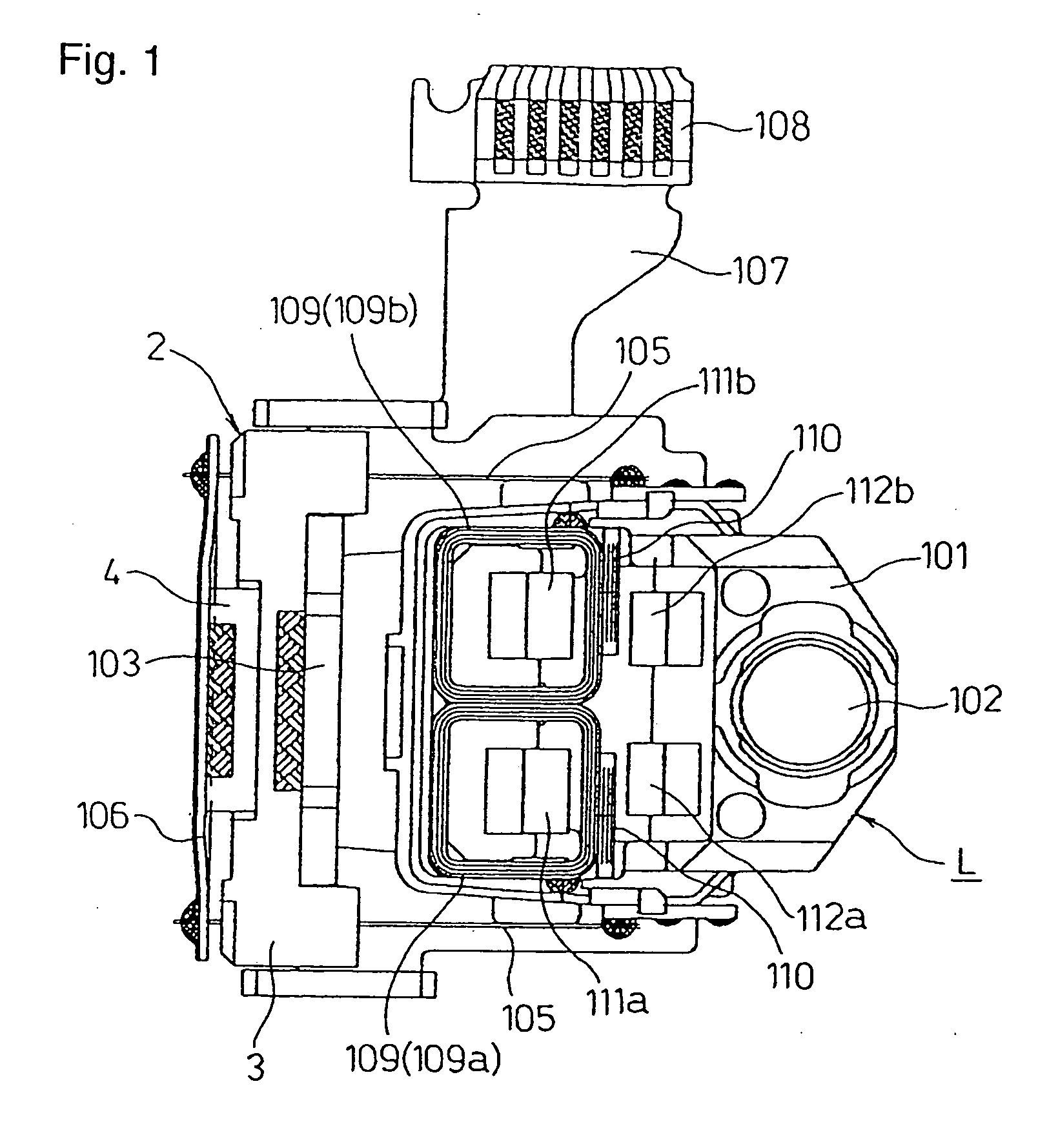
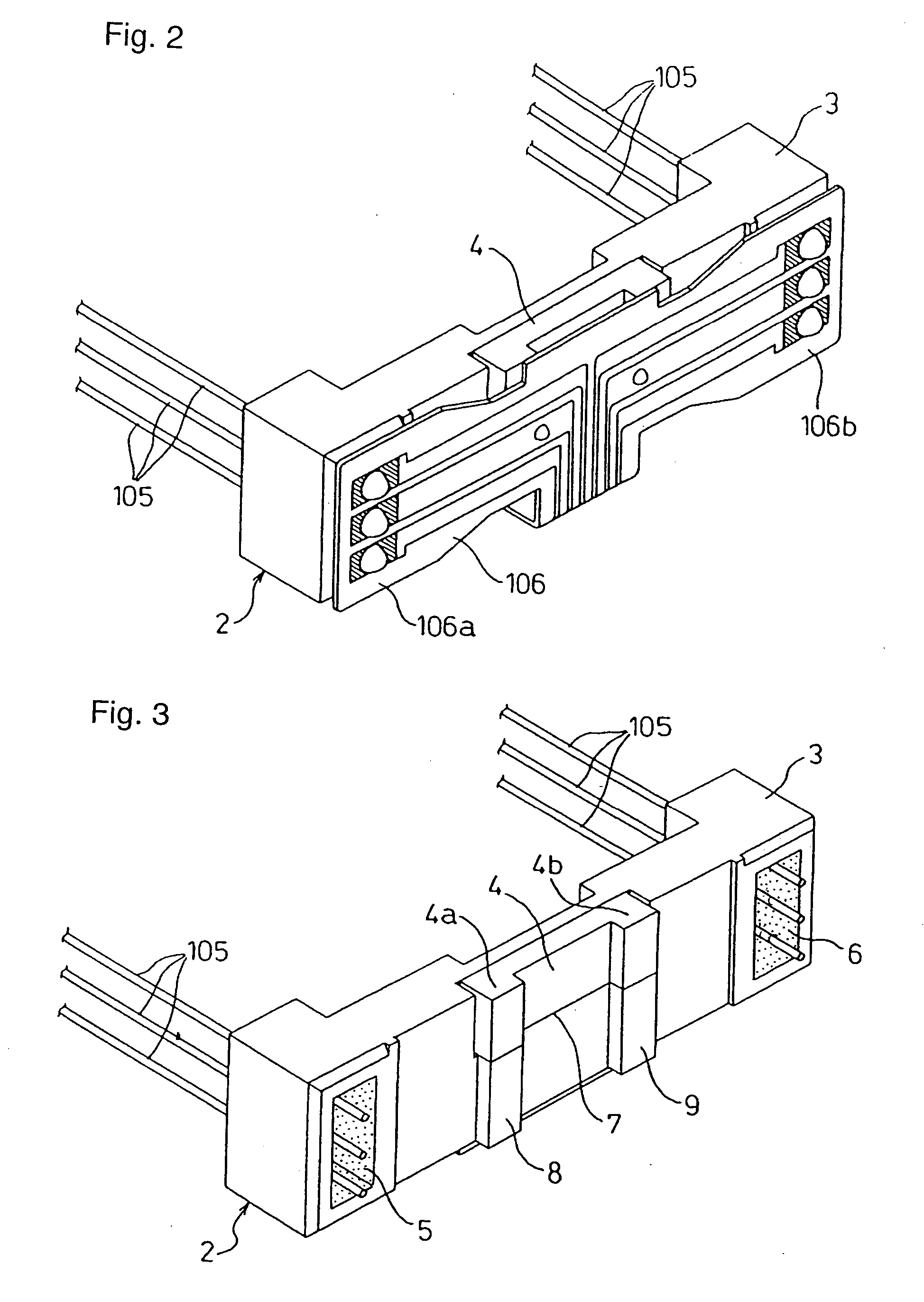
In an optical pick-up device in which a supporting member for fixing one end of each of suspension members is arranged on a rear side of a suspension holder fixed to a yoke base and an object lens is displaced by servo-controlling a lens holder for holding the other ends of the suspension members in an electromagnetic driving manner to adjust the irradiation position of a beam spot on an optical disk, the suspension holder is formed of a plurality of members having different coefficients of linear expansion. In addition, when forming the suspension holder, a second member having a coefficient of linear expansion higher than that of a first member fixed to the yoke base is arranged on the rear side of the suspension holder, and the first member and the second member are integrated into one body.

[Embodiments]

Hereinafter, an embodiment according to the present invention will be described with reference to FIGS. 1 to 5. In addition, the same reference characters represent the same c...


PUM

PropertyMeasurementUnit
temperatureaaaaaaaaaa
general structureaaaaaaaaaa
rigidityaaaaaaaaaa

Abstract

The present invention provides an optical pick-up device capable of suppressing the inclination of a lens actuator in the jitter direction caused by the variation of the ambient temperature thereof to stably record or reproduce information to or from an optical disk. In the optical pick-up device, a supporting member 106 for fixing one end of each of suspension members 105 is arranged on a rear side of a suspension holder 2 fixed to a yoke base 103, and an object lens 102 is displaced by servo-controlling a lens holder 101 for holding the other ends of the suspension members in an electromagnetic driving manner to adjust the irradiation position of a beam spot on an optical disk. The suspension holder 2 is formed of a plurality of members having different coefficients of linear expansion, and the members having a higher coefficient of linear expansion are arranged on the rear side of the suspension holder 2. Therefore, the supporting member 106 is displaced by the linear expansion of the members having a higher coefficient of linear expansion according to the variation of temperature, thereby suppressing inclination of a lens actuator L.

Description

BACKGROUND OF THE INVENTION 1. Field of the Invention The present invention relates to an optical pick-up device for recording or reproducing information to or from an optical disk that is provided in an optical disk device for driving optical discs (for example, CD-R / RW and DVD-R / -RW / RAM / +R / +RW) as recording media for recording a large amount of information by information processing apparatuses, such as various computer systems. 2. Description of the Related Art An optical pick-up device in an optical disk device for driving optical disks is constructed by a combination of various components of an optical system to form a beam spot on a recording surface of an optical disk. FIG. 6 is a view schematically illustrating the general structure of a conventional optical pick-up device. In FIG. 6, reference character A denotes an actuator assembly of the optical pick-up device, reference character B denotes a semiconductor laser hologram unit for DVD, and reference character C denotes...

Claims


Application Information

Patent Timeline
Patent Type & Authority Applications(United States)
IPC IPC(8): G11B7/09G11B7/00G11B7/08G11B7/095G11B7/12
CPCG11B7/0932G11B7/12G11B7/0935G11B7/0933G11B7/08G11B7/09
Inventor KABASAWA, HIDETOSHI
Owner TEAC CORP
Why Eureka
Try Eureka