
RZ-AMI optical transmitter module

a technology of optical transmitter and optical transmitter module, which is applied in the direction of optics, electrical equipment, instruments, etc., can solve the problems of conventional optical transmitter module cost, additional plurality of rf drivers, and high cost of conventional optical transmitter modul

Inactive Publication Date: 2005-04-14
SAMSUNG ELECTRONICS CO LTD
View PDF6 Cites 30 Cited by
  • Summary
  • Abstract
  • Description
  • Claims
  • Application Information

AI Technical Summary

Benefits of technology

[0016] Accordingly, the present invention has been made to reduce or overcome the above-mentioned problems occurring in the prior art. One object of the present invention is to provide an optical transmitter module having only one Mach-Zehnder modulator.

Problems solved by technology

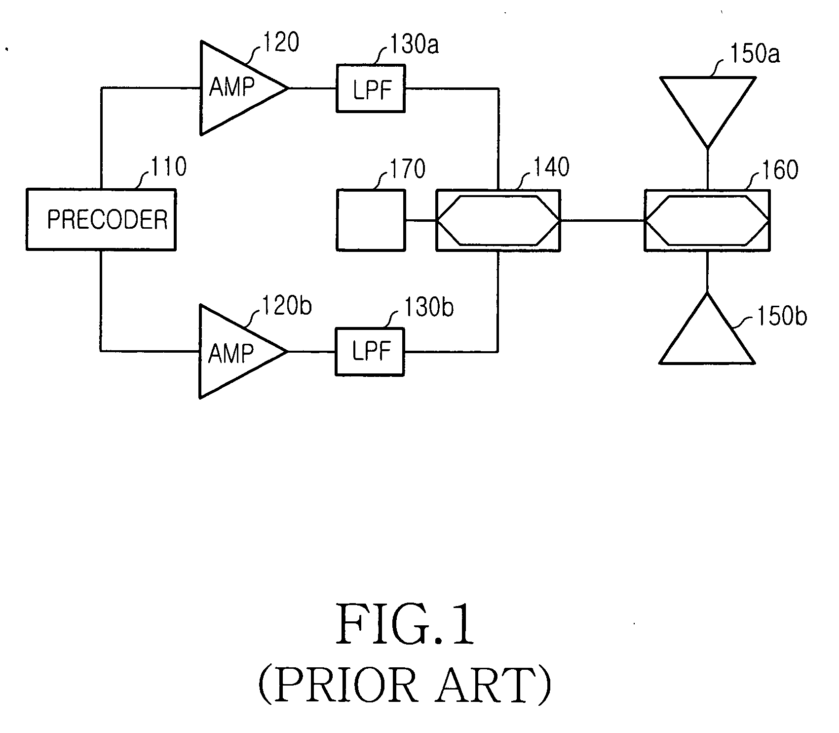
Therefore, the cost of a conventional optical transmitter module is high.
Also, the conventional optical transmitter module has many limitations, including that an additional plurality of RF drivers are required, thus it is necessary to synchronize operations of the two Mach-Zehnder modulators.

Method used


Image

  • RZ-AMI optical transmitter module
  • RZ-AMI optical transmitter module
  • RZ-AMI optical transmitter module

Examples


Embodiment Construction

[0026] Hereinafter, preferred embodiments of an RZ-AMI optical transmitter module according to the present invention will be described with reference to the accompanying drawings. For the purposes of clarity and simplicity, a detailed description of known functions and configurations incorporated herein will be omitted as it may make the subject matter of the present invention unclear.

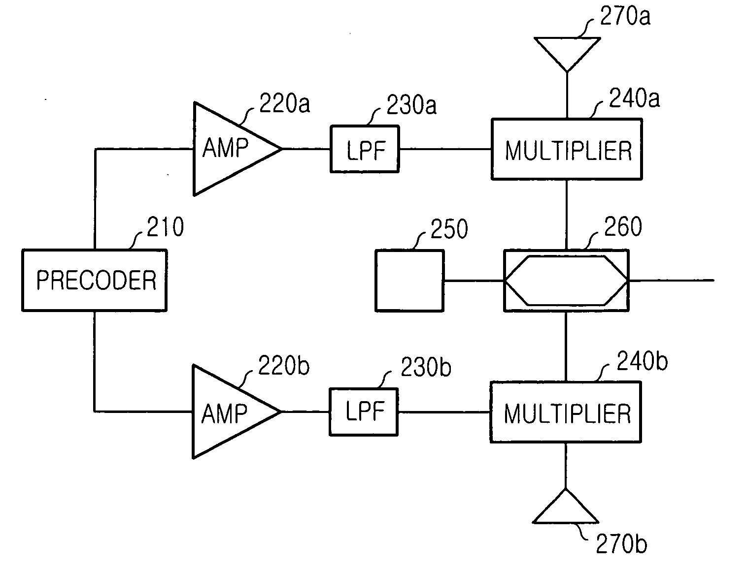
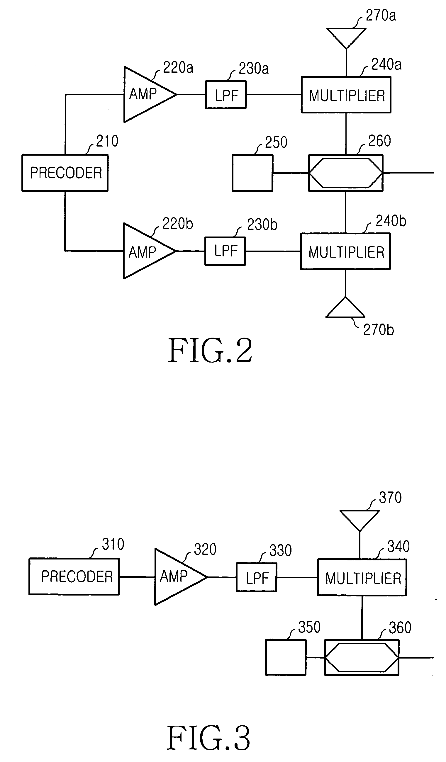
[0027]FIG. 2 is a block diagram of an optical transmitter module including multipliers according to a first embodiment of the present invention. FIGS. 4 to 6 are eye diagrams for explaining an operation characteristic of the optical transmitter module shown in FIG. 2. Referring to FIG. 2 and FIGS. 4 to 6, the optical transmitter module includes a precoder 210, amplifiers 220a and 220b, converters 230a and 230b, frequency generators 270a and 270b, multipliers 240a and 240b, a light source 250, and a Mach-Zehnder modulator 260.

[0028] The precoder 210 includes a one-bit delay device and an exclusive-OR ...


PUM

PropertyMeasurementUnit
frequencyaaaaaaaaaa
half frequencyaaaaaaaaaa
transmission speedaaaaaaaaaa

Abstract

Disclosed is an optical transmitter module comprising: a precoder to generate an encoded binary signal from an electric signal; an amplifier to amplify the binary signal; a converter to convert the amplified encoded binary signal into a limited ternary signal; a frequency generator to generate a sine wave having a predetermined frequency; a multiplier to multiply the ternary signal using the sine wave; a light source to generate a coherent CW light having a constant intensity; and a Mach-Zehnder modulator to modulate the CW light according to the ternary signal from the multiplier.

Description

CLAIM OF PRIORITY [0001] This application claims priority to an application entitled “RZ-AMI Optical Transmitter Module,” filed in the Korean Intellectual Property Office on Oct. 14, 2003 and assigned Serial No. 2003-71287, the contents of which are hereby incorporated by reference. BACKGROUND OF THE INVENTION [0002] 1. Field of the Invention [0003] The present invention relates to an optical transmission apparatus, and more particularly to a return-to-zero optical transmission apparatus which has a high receiving sensitivity and opposes the nonlinearity aspects of an optical fiber. [0004] 2. Description of the Related Art [0005] In general, a dense wavelength division multiplexing (hereinafter, referred to as “DWDM”) optical transmission system transmits an optical signal (which includes a plurality of channels having different wavelengths from each other) through one optical fiber. Accordingly, the DWDM optical transmission system has improved transmission efficiency. DWDM optical...

Claims


Application Information

Patent Timeline
Patent Type & Authority Applications(United States)
IPC IPC(8): H04B10/516G02F1/035H04B10/524H04B10/54H04B10/61
CPCH04B10/5055H04B10/505H04B10/50H04B10/516
Inventor KIM, HOONOH, YUN-JEHWANG, SEONG-TAEK
Owner SAMSUNG ELECTRONICS CO LTD
Learn More