Power cord plug and jack retainer and hanger

a technology of power cord and jack retainer, which is applied in the direction of curtain suspension device, machine support, coupling device connection, etc., to achieve the effect of convenient insertion, convenient retention and convenient inserting of power cord plugs

Inactive Publication Date: 2005-04-14
DECKER SELDEN M
View PDF47 Cites 12 Cited by
  • Summary
  • Abstract
  • Description
  • Claims
  • Application Information

AI Technical Summary

Benefits of technology

[0004] An advantage of the present invention is that it is effective in holding a power cord plug and jack together.
[0005] In accordance with the present invention, the power cord plug may be a power cord plug of a power tool, implement, appliance or any other electrical apparatus which requires power. The jack may be connection of a power cord in the form of an extension cord or other power cord.
[0006] Another advantage of the present invention is that the retainer does not snag on other objects as it is pulled.
[0007] Another advantage of the present invention is that it is easy to insert the power cord plug and jack into the retainer.
[0008] Another advantage of the present invention is that the retainer is effectively held connected together by pins and slots in connection with resilient forces.
[0009] Another advantage of the present invention is that the cord may be conveniently inserted by means of a flap and readily retained therein by the flap.

Problems solved by technology

Unfortunately, as the worker, homeowner or other user of a power tool, implement or appliance moves around, the power cord plug often pulls out of the jack of an extension cord or, if multiple extension cords are connected together, the plug of one extension cord pulls out of the jack of the other extension cord.
This is very disruptive of the effort to try to accomplish whatever is being accomplished with the power tool, implement or appliance.

Method used


Image

  • Power cord plug and jack retainer and hanger
  • Power cord plug and jack retainer and hanger
  • Power cord plug and jack retainer and hanger

Examples


Embodiment Construction

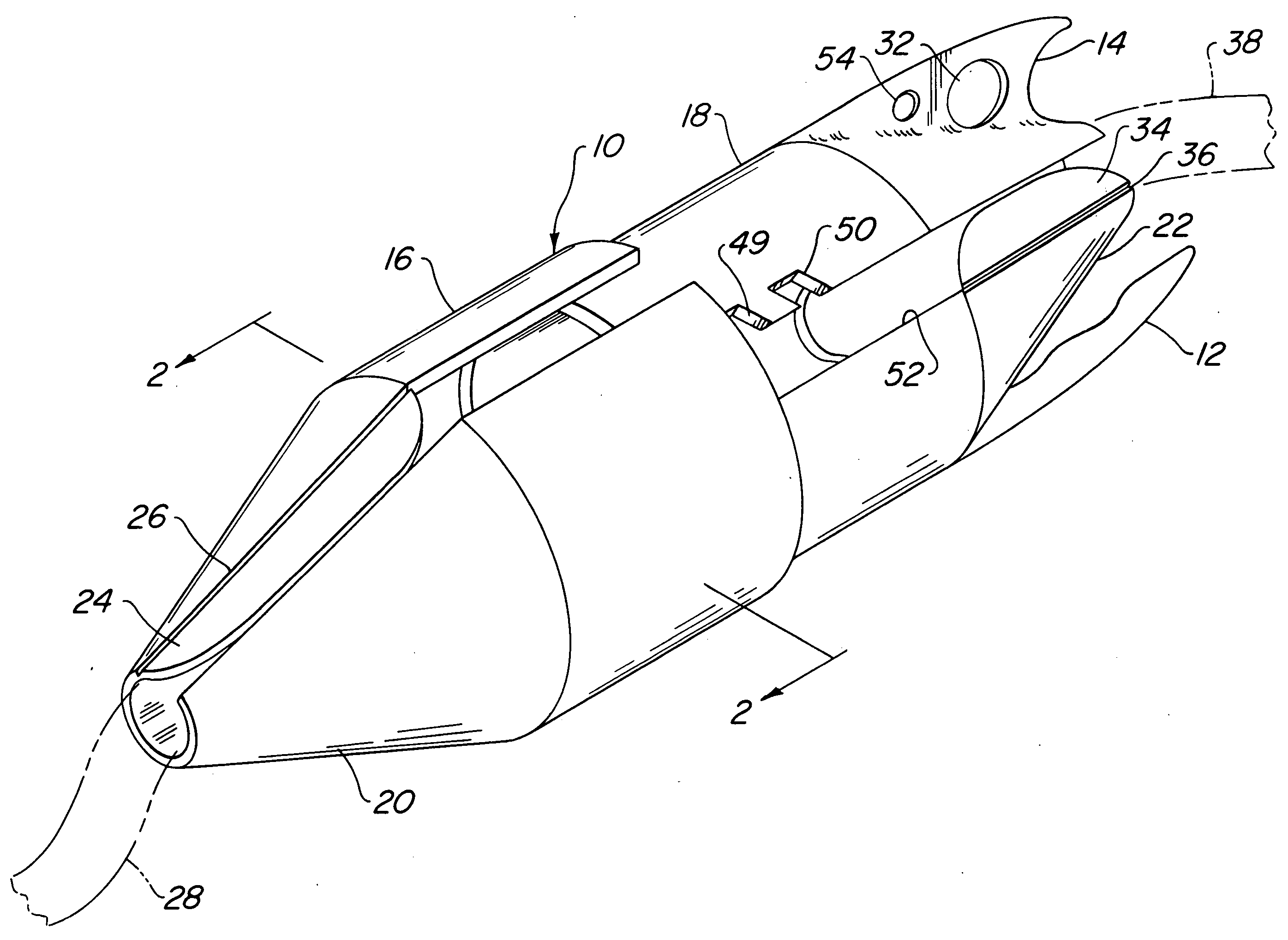
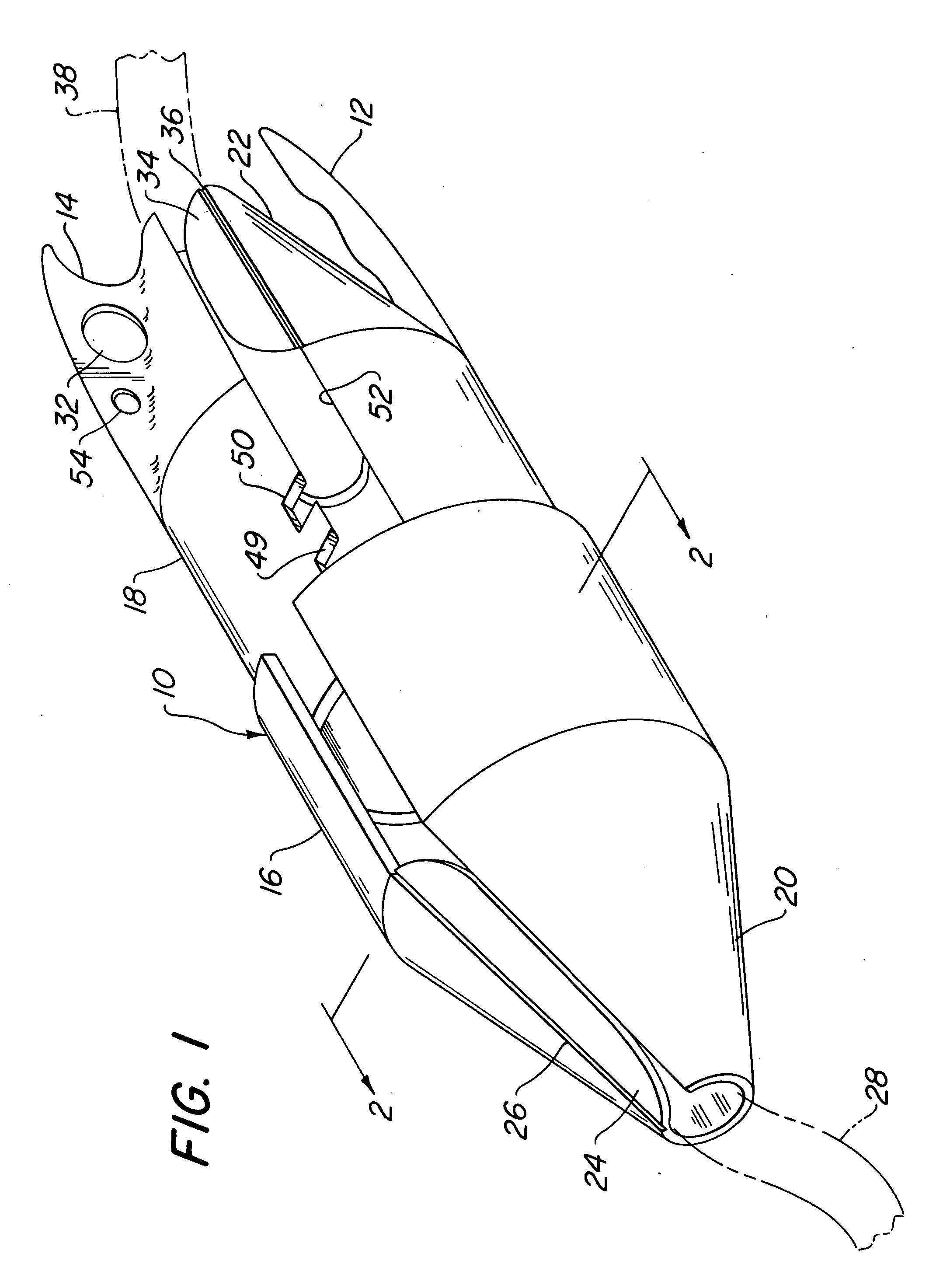
[0032] Referring now to the drawings wherein like numerals indicate like elements, there is shown in FIGS. 1 and 5 a power cord plug and jack retainer 10 which includes hangers 12 and 14. Power cord plug and jack retainer 10 is comprised of a first section 16 and a second section 18. First section 16 is female in that it receives second section or male section 18.

[0033] Referring now more particularly to FIG. 1, it may be seen that first section 16 is provided with a conical end portion 20 and second section 18 is provided with a conical end portion 22. The conical end portions prevent snagging on other objects when the power cord plug and jack retainer is pulled while retaining a plug and a jack of two power cords.

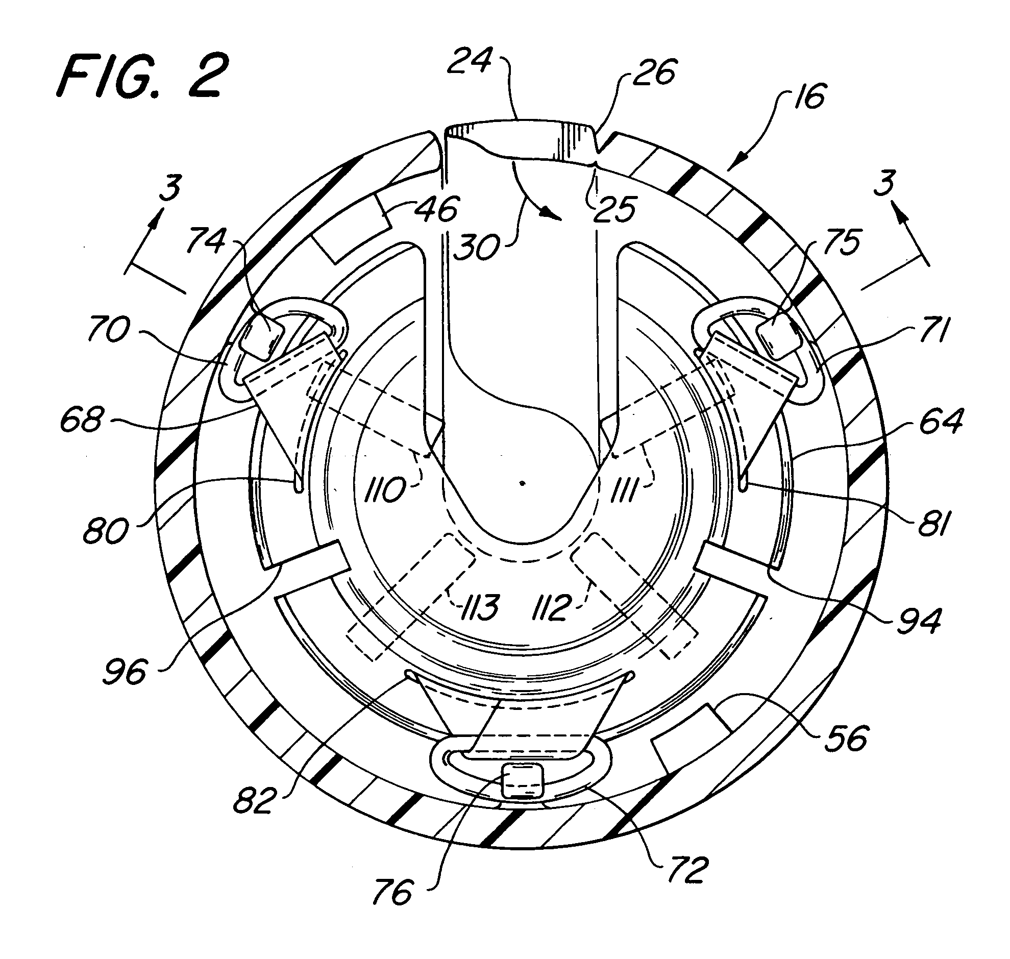
[0034] Conical end portion 20 is provided with a flap 24 which is integrally connected with conical end portion 20 but separated from conical end portion 20 by an external groove 26 which only partially penetrates the material comprising conical end portion 20 and flap ...


PUM


Abstract

A power cord plug and jack retainer includes a first and second mating sections. The first and second sections are adapted to mate such that the first section is female and the second section is male. The sections are provided with rhombic shaped pins and slots which lock in place against resilient forces provided by resilient pads and resilient straps. The retainer is provided with conical end portions to prevent snagging but is provided with hooks on the jack side of the conical portion for hooking the retainer on a suitable support such as a belt, ladder, branch or any other suitable support. The second section with the hooks on the conical portion may be used to hang a cord of a power tool or any other item having a cord with an enlarged portion. Any tool may be hung by a rope by placing a knot in the rope and hanging it from the second section.

Description

FIELD OF THE INVENTION [0001] The present invention relates to a power cord plug and jack retainer and hanger. More particularly, the present invention relates to a power cord plug and jack retainer and hanger which is effective in holding a power cord plug and jack together and also effective in enabling the hanging of the retainer from a support. BACKGROUND OF THE INVENTION [0002] Power cords in the form of cords on tools, implements and appliances and their use in connection with extension cords, or multiple extension cords, is widespread. Carpenters and other journeymen working with electric power tools often need to plug a power tool into an extension cord and move about a job site. Unfortunately, as the worker, homeowner or other user of a power tool, implement or appliance moves around, the power cord plug often pulls out of the jack of an extension cord or, if multiple extension cords are connected together, the plug of one extension cord pulls out of the jack of the other e...

Claims


Application Information

Patent Timeline
Patent Type & Authority Applications(United States)
IPC IPC(8): H01R13/625H01R13/639
CPCH01R13/6392H01R13/625
Inventor DECKER, SELDEN M.
Owner DECKER SELDEN M
Why Eureka
Try Eureka