Table reference type predistorter

a table reference and predistorter technology, applied in the direction of amplifier modifications to reduce non-linear distortion, transmission monitoring, baseband system details, etc., can solve the problems of large error, wide-band distortion, and inability to determine the correct predistortion coefficien

Inactive Publication Date: 2005-04-14
FUJITSU LTD
View PDF3 Cites 77 Cited by
  • Summary
  • Abstract
  • Description
  • Claims
  • Application Information

AI Technical Summary

Problems solved by technology

In a predistorter which compares an original signal and part of the output signal of an amplifier to determine a predistortion coefficient, there was a problem in that a correct predistortion coefficient cannot be determined if a frequency amplitude deviation exists (when frequency characteristics of amplitude are not flat), or if a delay error exists between the original signal and the output signal of the amplifier.
There was another problem in that it takes time to converge a predistortion coefficient, and an error becomes large in the region where the envelope amplitude of the original signal is small, the fluctuations of the envelope are large, and the absolute value of the differential at a certain time interval is large.
In such a case, as the result of multiplying the distortion compensation coefficient, a signal which becomes smaller like a spike in shape and is close to 0 is generated, thereby giving rise to a wide-band distortion.
When there exists no frequency amplitude deviation, a problem takes place in that this distortion compensation coefficient is multiplied to the original signal, so the input signal to the amplifier 100 becomes smaller, and the output error of the amplifier 100 becomes larger.
Because the emergence frequency is small at the position in which the absolute value of time differential is large, as described in FIG. 24, it is considered that it takes time to converge the distortion compensation coefficient at such a position and that errors accumulate and spread.
In such a case, a spike-shaped singular point of the distortion compensation coefficient emerges at only one position as shown in FIG. 25, and a problem takes place in that no correct distortion compensation effect can be obtained.

Method used


Image

  • Table reference type predistorter
  • Table reference type predistorter
  • Table reference type predistorter

Examples


first embodiment

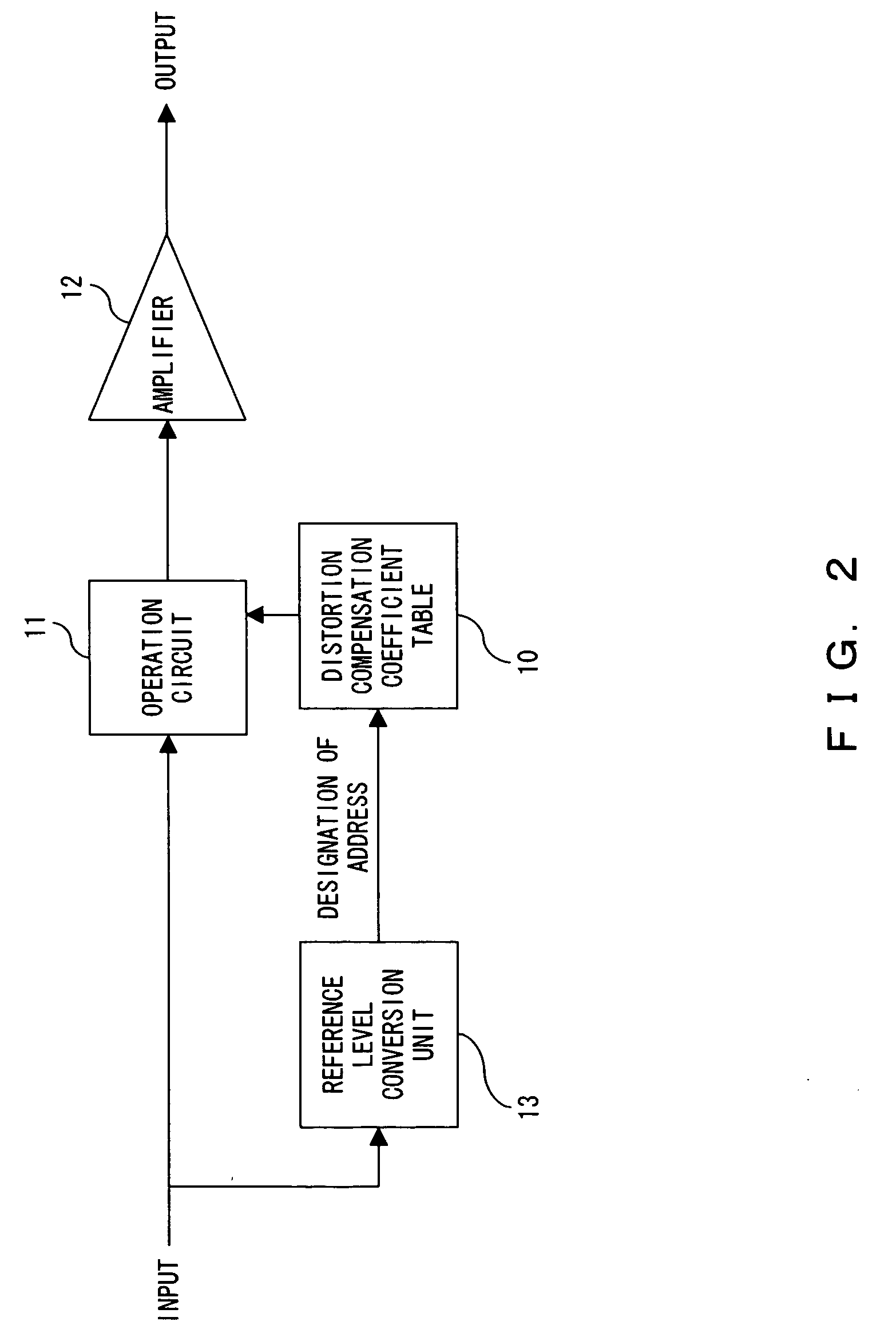
[0072]FIG. 3 shows the predistortion method in a In FIG. 3, in the same way as in FIG. 2, the distortion compensation coefficient and the input signal stored in the distortion compensation coefficient table 15 are multiplied by the multiplication circuit 16, and the multiplication result is given to the amplifier 17, and the output of the amplifier 17 becomes a transmission output signal via the directional coupler 18.

[0073] The input signal and part of the transmission output signal, i.e. part of the output of the directional coupler 18 are compared by the comparison computing unit 22, and errors are calculated, and the storage contents of the distortion compensation coefficient table 15 are updated by the coefficient making unit 23, for example, by using the LMS algorithm.

[0074] The update of a distortion compensation coefficient using this LMS algorithm is described in detail in the following prior application of the applicant.

[0075] Document 4: International publication Wo 01...

second embodiment

[0080]FIG. 6 shows the predistortion method in a In FIG. 6, in the same way as the second conventional example described in FIG. 19, reference is made to the distortion compensation coefficient table using both the envelope amplitude value and the time differential of the envelope value as an address, but in FIG. 6, the comparison rounding-up unit 26 is provided between the envelope time-differential calculation unit 25 and the distortion compensation coefficient table 15.

[0081] Then, the absolute value of the envelope time differential is compared with the set value set in advance. In the region where the absolute value of the envelope time differential is large as described in FIG. 24 and FIG. 25, and a spike-shaped distortion compensation coefficient emerges because the emergence frequency is small, the distortion compensation coefficient whose the range of an absolute value is smaller is used, so the absolute value of the envelope time differential is rounded down, and the roun...

fourth embodiment

[0090]FIG. 10 shows a first example of operation in a In FIG. 10, power calculation or the through unit 32 is used as a concrete example of the operation circuit 30 shown in FIG. 9, and power conversion of the envelope amplitude value as the calculation result of the envelope amplitude calculation unit 20 is carried out, and the conversion result is given to the set-value comparison / rounding-up unit 21.

[0091] Basically, by squaring the envelope amplitude value and converting it into a power value, the resolution of the part in which the envelope amplitude value is large can be improved, so when it is judged by the mean-value calculation integral circuit threshold comparison unit 31 that the mean power of the signal is larger than the threshold in which the mean power of the signal is large and in which power calculation is conducted by the power calculation or a trough unit 32, change-over information to conduct the power calculation is given to the power calculation or the through...


PUM


Abstract

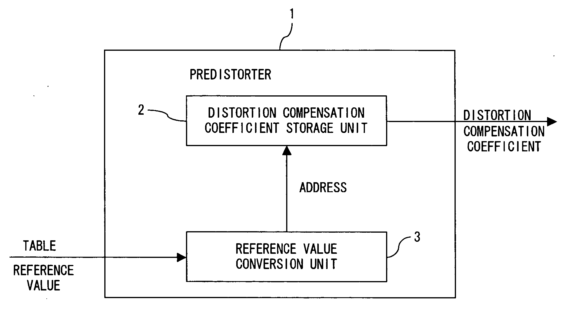
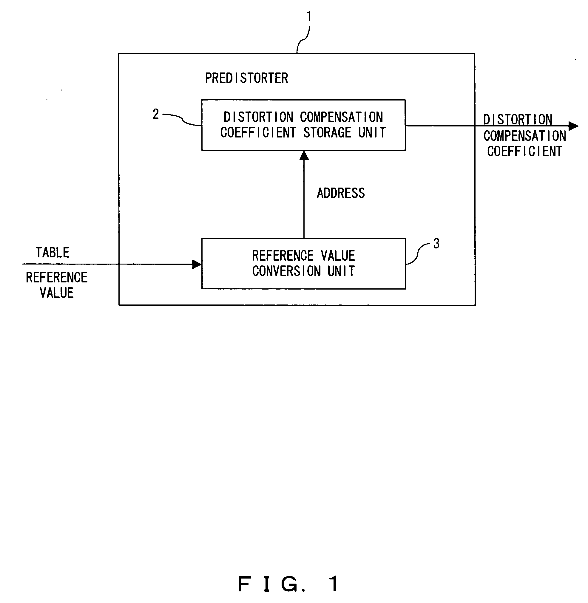
The purpose of the present invention is to compensate the distortion of an amplifier by a predistorter which compensates the distortion of a power amplifier even when a frequency amplitude deviation exists. The predistorter comprises a distortion compensation coefficient storage unit for storing a distortion compensation coefficient corresponding to the reference value using the characteristic quantity of the envelope of a transmission signal before being inputted to the power amplifier as a reference value; and a reference value conversion unit for converting the characteristic quantity into a predetermined value according to the size of the characteristic quantity, and when the characteristic quantity is, for example, the amplitude value of an envelope and the amplitude value is small, that value is rounded up, for example, to an upper-limit value within a linear range of the amplifier.

Description

CROSS REFERENCE TO RELATED APPLICATION [0001] This application is a continuation of an International Application No. PCT / JP02 / 05373, which was filed on May 31, 2002.BACKGROUND OF THE INVENTION [0002] 1. Field of the Invention [0003] The present invention relates to a power amplifier for radio transmission which is used for a cellular phone and digital broadcasting, and more specifically to a predistorter which reduces the distortion of the power amplifier. [0004] 2. Description of the Related Art [0005] A predistorter is available as a linear compensator for an amplification circuit having nonlinear characteristics. In a predistorter, the suppression of a distortion of an amplifier is realized, for example, by multiplying a coefficient according to the envelop of an original signal to be transmitted by the original signal as a predistortion coefficient for canceling the distortion of the amplifier. This predistortion coefficient, namely the distortion compensation coefficient is det...

Claims


Application Information

Patent Timeline
Patent Type & Authority Applications(United States)
IPC IPC(8): H03F1/32H04L27/36
CPCH04L27/368H03F1/3247
Inventor MANIWA, TORUKUBO, TOKURONAGATANI, KAZUOISHIKAWA, HIROYOSHI
Owner FUJITSU LTD
Why Eureka
Try Eureka