
Cell reselection with power scan and parallel decoding

a cell and power scan technology, applied in the field of communication, can solve the problems of long time and miss any paging messages sent, and achieve the effect of reducing down time and improving performan

Active Publication Date: 2005-04-14
QUALCOMM INC
View PDF12 Cites 102 Cited by
  • Summary
  • Abstract
  • Description
  • Claims
  • Application Information

AI Technical Summary

Benefits of technology

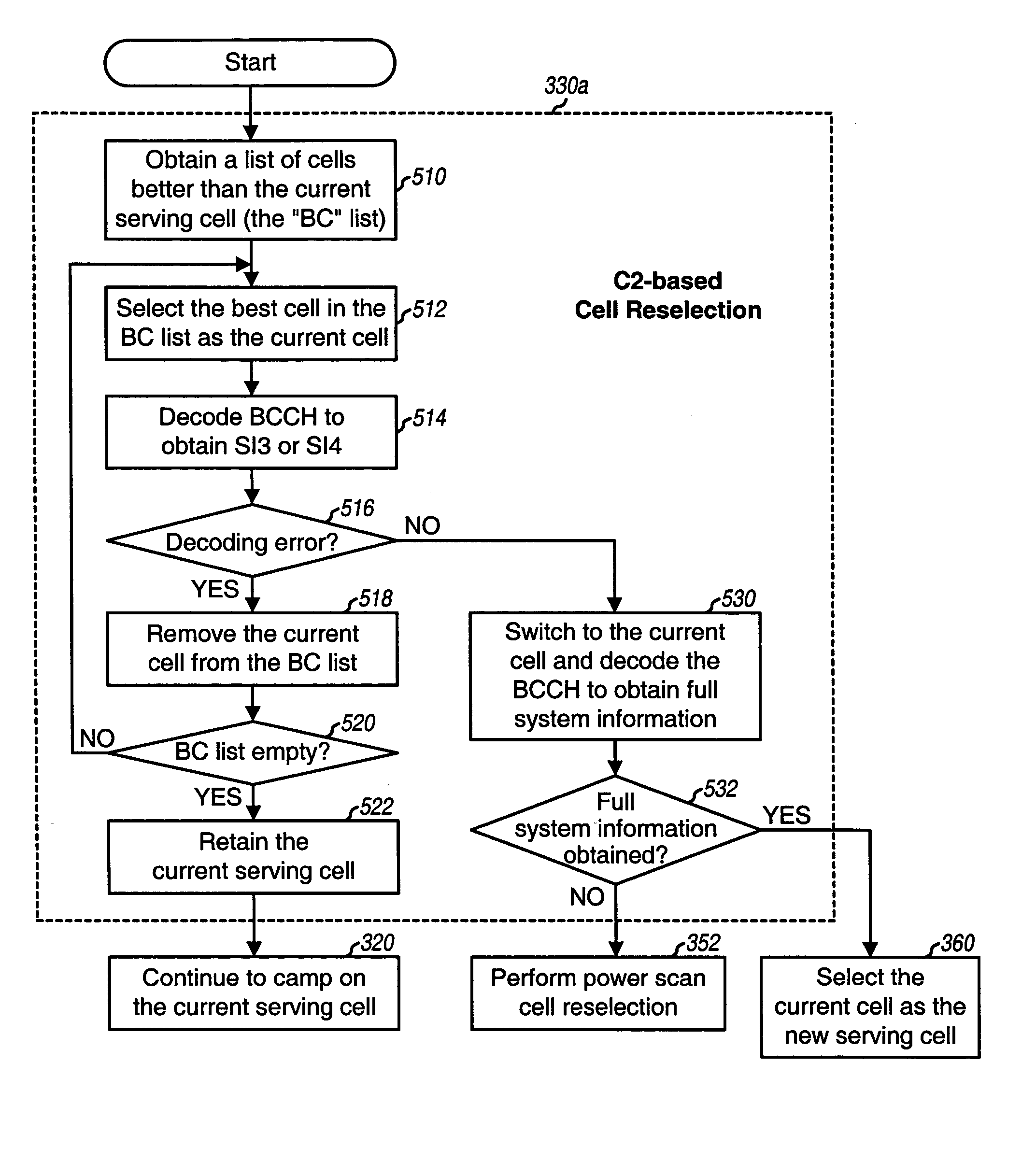
Techniques for performing cell reselection with power scan and / or parallel decoding are provided herein. These techniques may reduce down time and provide improved performance. Upon power on, a terminal performs cell selection to find the most suitable cell that the terminal can camp on and receive communication service. The terminal selects this most suitable cell as the serving cell and camps on this cell if the terminal is in idle mode. The terminal may thereafter perform cell reselection to select another suitable cell to receive service. Cell reselection may be required for any number of reasons such as, for example, if a better cell is found, if the terminal can no longer camp on the current serving cell, and so on. The terminal performs “C2-based” cell reselection if a better cell is found and “non-C2 based” cell reselection for any other reason. In an embodiment, the terminal performs “power scan” cell reselection if the C2-based or non-C2 based cell reselection fails. In other embodiments, the power scan cell reselection may be triggered by some other events or conditions.

Problems solved by technology

For cell reselection where the initial reselection fails or there is no information on neighbor cells, the terminal may need to obtain received signal strength measurements and need to gather pertinent system information for new cells, both of which typically require a long period of time to perform.
During the time that the terminal is performing these tasks, it is not able to receive service from the system and would also miss any paging messages sent to it, both of which are highly undesirable.

Method used


Image

  • Cell reselection with power scan and parallel decoding
  • Cell reselection with power scan and parallel decoding
  • Cell reselection with power scan and parallel decoding

Examples


Embodiment Construction

The word “exemplary” is used herein to mean “serving as an example, instance, or illustration.” Any embodiment or design described herein as “exemplary” is not necessarily to be construed as preferred or advantageous over other embodiments or designs.

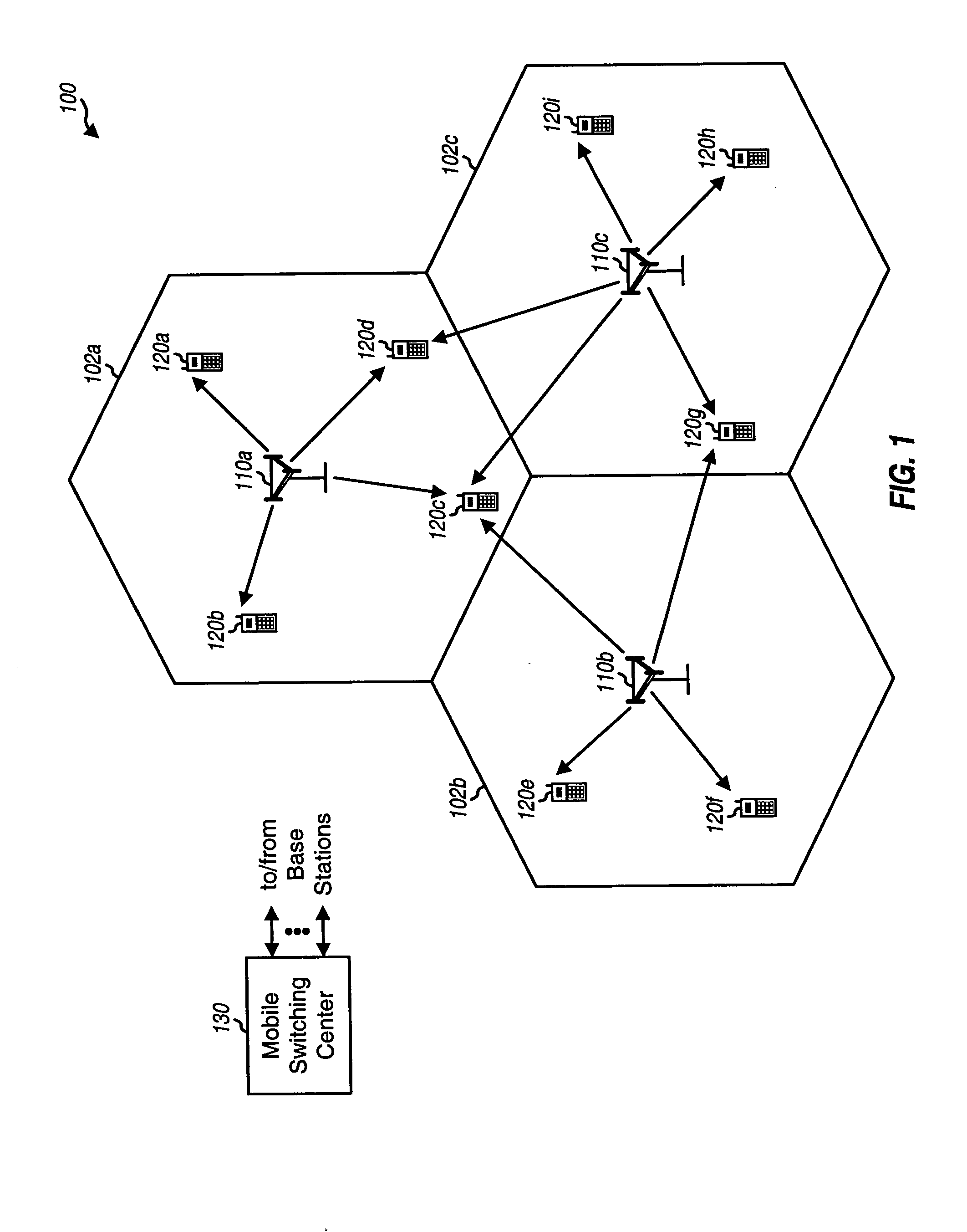
FIG. 1 shows a wireless communication system100 with a number of base stations 110 that provide communication service for a number of terminals 120. A base station is a fixed station and may also be referred to as a base transceiver station (BTS), a Node B, an access point, or some other terminology. Terminals 120 are typically dispersed throughout the system. A terminal may be fixed or mobile and may also be referred to as a mobile station (MS), a mobile equipment (ME), a user equipment (UE), a wireless communication device, or some other terminology. A mobile switching center (MSC) 130 provides coordination and control for base stations 110 and further controls the routing of data to / from the terminals served by these base stations....


PUM


Abstract

Upon power on, a terminal performs cell selection, finds the most suitable cell to receive communication service, and camps on this cell (the serving cell). The terminal thereafter performs “C2-based” cell reselection if a better cell is found, “non-C2 based” cell reselection if the current serving cell cannot be camped on, “power scan” cell reselection if the C2-based or non-C2 based cell reselection fails, and cell selection if the power scan cell reselection fails. For the power scan cell reselection, the terminal initially performs a power scan and obtains received signal strength measurements for a list of RF channels. This list includes fewer than all RF channels evaluated by the cell selection. The terminal then acquires and decodes the N strongest RF channels, preferably in parallel, to find a suitable cell. The terminal selects a suitable cell, if found, with the highest C2 value as the new serving cell from which to receive service.

Description

BACKGROUND I. Field The present invention relates generally to communication, and more specifically to techniques for performing cell reselection in a wireless communication system. II. Background In a Global System for Mobile Communications (GSM) system, a terminal that is just powered on or has just lost coverage searches for suitable cells from which the terminal can receive communication service. A “cell” can refer to a base station in the system and / or the coverage area of the base station, depending on the context in which the term is used. A “suitable” cell is one that the terminal can receive service on. GSM defines a set of criteria that a cell must meet in order to be deemed a suitable cell. If a suitable cell is found, then the terminal performs registration with the cell, if necessary. The terminal then “camps” on the cell if the terminal is in an idle mode and not actively communicating with the cell. While camped on the cell, the terminal performs tasks as specifie...

Claims


Application Information

Patent Timeline
IPC IPC(8): H04W36/08H04W88/06
CPCH04W88/06H04W60/04
Inventor RICK, ROLANDCONSTANDSE, RODGER
Owner QUALCOMM INC
Learn More