Continuously variable transmission

a transmission and variable technology, applied in the field of transmissions, can solve the problems of difficult shifting of the rotational axis of each of the traction rollers, difficult use of iris plates, and limited success of traditional solutions

Inactive Publication Date: 2005-04-14
FALLBROOK INTPROP COMPANY
View PDF51 Cites 93 Cited by
  • Summary
  • Abstract
  • Description
  • Claims
  • Application Information

AI Technical Summary

Problems solved by technology

However, the success of these traditional solutions has been limited.
However, the use of iris plates can be very complicated due to the large number of parts which are required to adjust the iris plates during shifting the transmission.
Another difficulty with this transmission is that it has a guide ring which is configured to be predominantly stationary in relation to each of the rollers.
Since the guide ring is stationary, shifting the axis of rotation of each of the traction rollers is difficult.
Yet another limitation of this design is that it requires the use of two half axles, one on each side of the rollers, to provide a gap in the middle of the two half axles.
The use of two axles is not desirable and requires a complex fastening system to prevent the axles from bending when the transmission is accidentally bumped, is as often the case when a transmission is employed in a vehicle.
Yet another limitation of this design is that it does not provide for an automatic transmission.

Method used


Image

  • Continuously variable transmission
  • Continuously variable transmission
  • Continuously variable transmission

Examples


Embodiment Construction

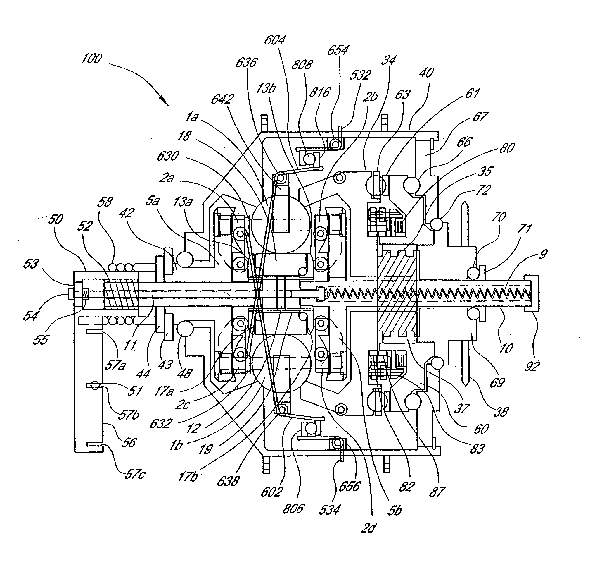
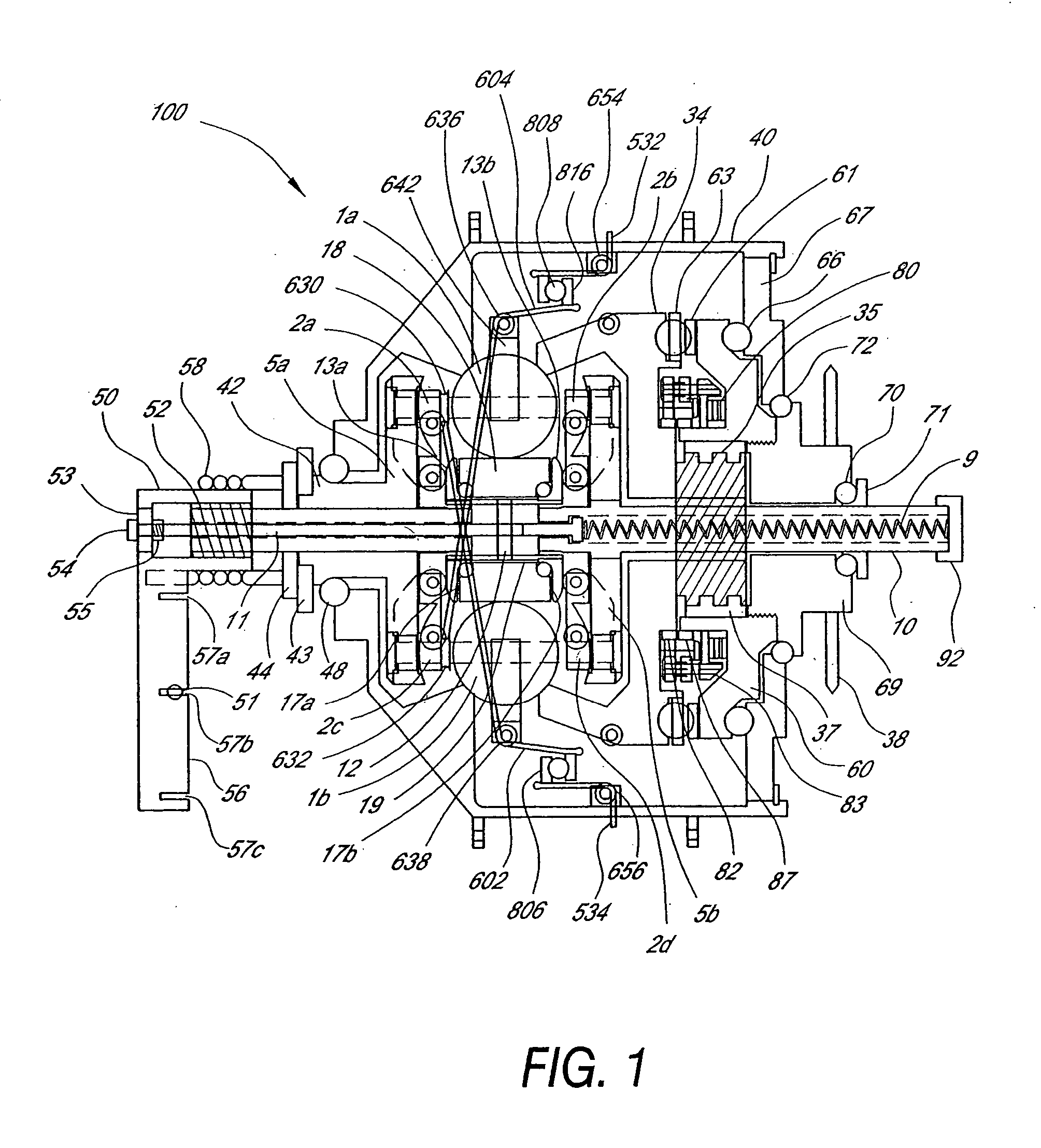
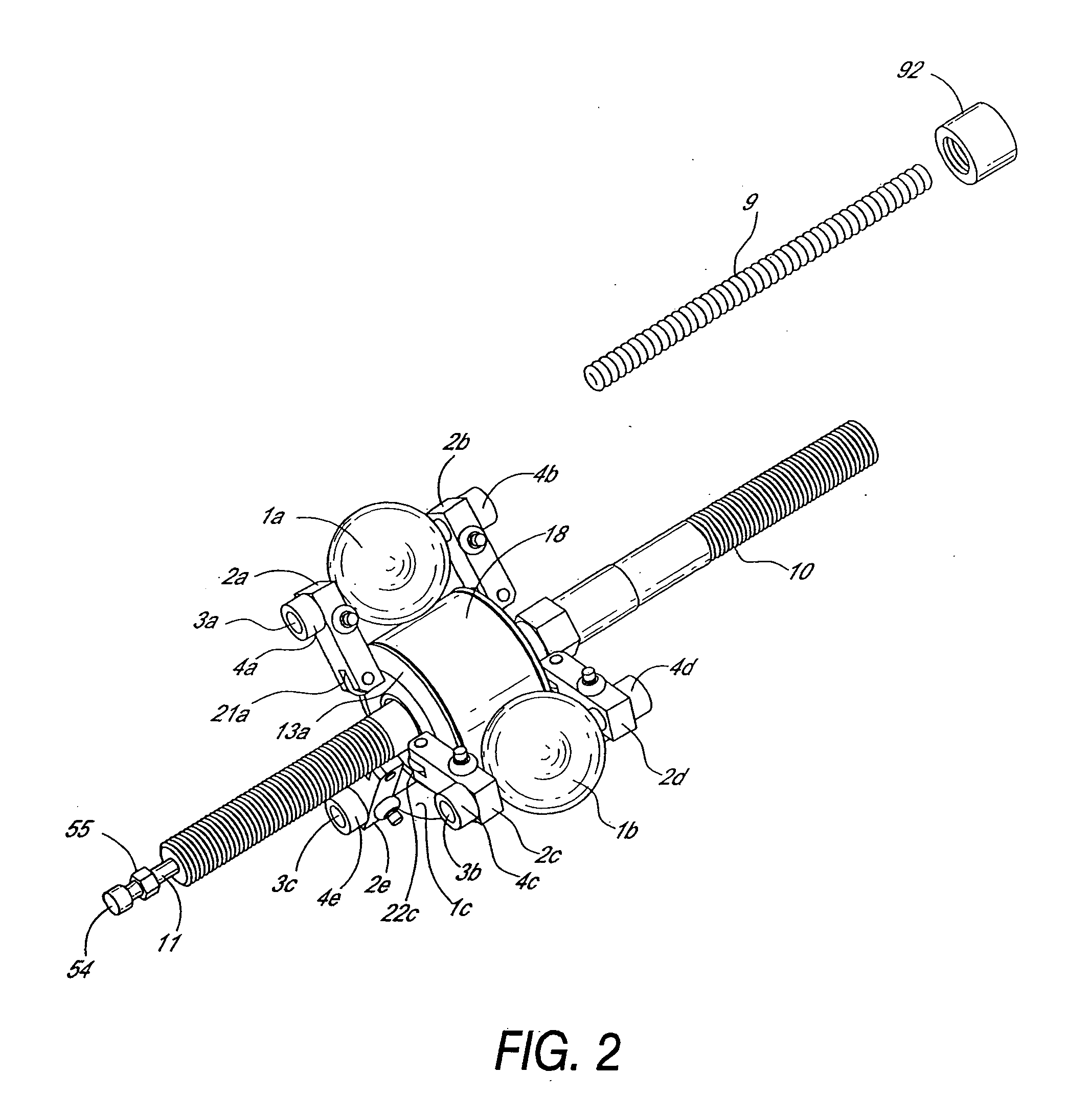
[0028] The following detailed description is directed to certain specific embodiments of the invention. However, the invention can be embodied in a multitude of different ways as defined and covered by the claims. In this description, reference is made to the drawings wherein like parts are designated with like numerals throughout. Furthermore, embodiments of the invention may include several novel features, no single one of which is solely responsible for its desirable attributes or which is essential to practicing the inventions herein described.

[0029] The present invention includes a continuously variable transmission that may be employed in connection with any type of machine that is in need of a transmission. For example, the transmission may be used in (i) a motorized vehicle such as an automobile, motorcycle, or watercraft, (ii) a non-motorized vehicle such as a bicycle, tricycle, scooter, exercise equipment or (iii) industrial equipment, such as a drill press, power generat...


PUM


Abstract

A continuously variable transmission is disclosed for use in rotationally or linearly powered machines and vehicles. The single axle transmission provides a simple manual shifting method for the user. An additional embodiment is disclosed which shifts automatically dependent upon the rotational speed of the wheel. Further, the practical commercialization of traction roller transmissions requires improvements in the reliability, ease of shifting, function and simplicity of the transmission. The disclosed transmission may be used in vehicles such as automobiles, motorcycles, and bicycles. The transmission may, for example, be driven by a power transfer mechanism such as a sprocket, gear, pulley or lever, optionally driving a one way clutch attached at one end of the main shaft.

Description

RELATED APPLICATIONS [0001] This application is a continuation of, and incorporates by reference in its entirety, U.S. application Ser. No. 10 / 418,509, filed Apr. 16, 2003, which is a continuation of U.S. application Ser. No. 10 / 141,652, filed May 7, 2002, which is a continuation of U.S. application Ser. No. 09 / 695,757, filed Oct. 24, 2000, now U.S. Pat. No. 6,419,608, which issued Jul. 16, 2002.BACKGROUND OF THE INVENTION [0002] 1. Field of the Invention [0003] The field of the invention relates to transmissions. More particularly the invention relates to continuously variable transmissions. [0004] 2. Description of the Related Art [0005] In order to provide an infinitely variable transmission, various traction roller transmissions in which power is transmitted through traction rollers supported in a housing between torque input and output discs have been developed. In such transmissions, the traction rollers are mounted on support structures which, when pivoted, cause the engageme...

Claims


Application Information

Patent Timeline
Patent Type & Authority Applications(United States)
IPC IPC(8): B62M11/00F16H15/28F16H61/664
CPCB62M11/00F16H61/664F16H15/28
Inventor MILLER, DONALD C.
Owner FALLBROOK INTPROP COMPANY
Why Eureka
Try Eureka