Optimal selection of input torque considering battery utilization for a hybrid electric vehicle

Active Publication Date: 2005-04-14
GM GLOBAL TECH OPERATIONS LLC
View PDF9 Cites 328 Cited by
  • Summary
  • Abstract
  • Description
  • Claims
  • Application Information

AI Technical Summary

Benefits of technology

In another embodiment, an electrically variable transmission includes an input, an output and an electric machine having known coupling relationships, and an energy storage system. A preferred input torque for operating the electrically variable transmission is determined in accordance with the following steps. Current electrically variable transmission operating conditions, including input, output and electric machine speeds are determined. System constraints in electric machine torque, energy storage system power and input torque at current electrically variable transmission operating conditions are determined. A target output torque producible within the system constraints is provided. Aggregate system power loss

Problems solved by technology

Known systems do not optimize the power fl

Method used


Image

  • Optimal selection of input torque considering battery utilization for a hybrid electric vehicle
  • Optimal selection of input torque considering battery utilization for a hybrid electric vehicle
  • Optimal selection of input torque considering battery utilization for a hybrid electric vehicle

Examples


first embodiment

As illustrated in FIG. 10, in a first embodiment, a first battery cost factor term, SOC_Cost_Factor, penalizes charging at high states of charge (solid line 123 in FIG. 10) and penalizes discharging at low states of charge (broken line 121 in FIG. 10). A second battery cost factor term, Throughput Cost_Factor, captures the effect of battery usage and assigns appropriate penalties thereto (line 125 in FIG. 10). Battery usage is preferably measured in terms of average battery current (Amp-hr / hr), and a penalty placed on average battery current operating points that increases with higher battery current. Such cost factors are preferably obtained from data sets stored in table form within data structures in system controller 43. Such data sets are provided for reference by the routine in pre-stored table format. The product of the respective cost factors and battery power yields the cost function terms, Pcost_SOC and Pcost_throughput.

In this embodiment, the total subjective cost is det...

second embodiment

Referring to FIG. 12, in a second embodiment, the total subjective cost is determined as shown in block 200 as a function of battery power also using battery parameters which include the SOC and amp-hour per hour throughput to determine the battery costs or penalties. First, battery cost factors are determined using lookup tables based on the state of charge (SOC) of the batteries and the amp-hour per hour throughput of the batteries. Similar to the example above, SOC costs are determined with separate lookup tables as different values of SOC have different costs associated with charging or discharging. Since the sign convention is that positive battery power is discharging, when state of charge SOC is low, additional costs are applied to discharging situations by increasing the SOC positive cost factor as SOC decreases, as illustrated in block 202. When SOC is in the normal range or is high, there is no need to apply additional costs to discharging situations. Similarly, when the S...


PUM


Abstract

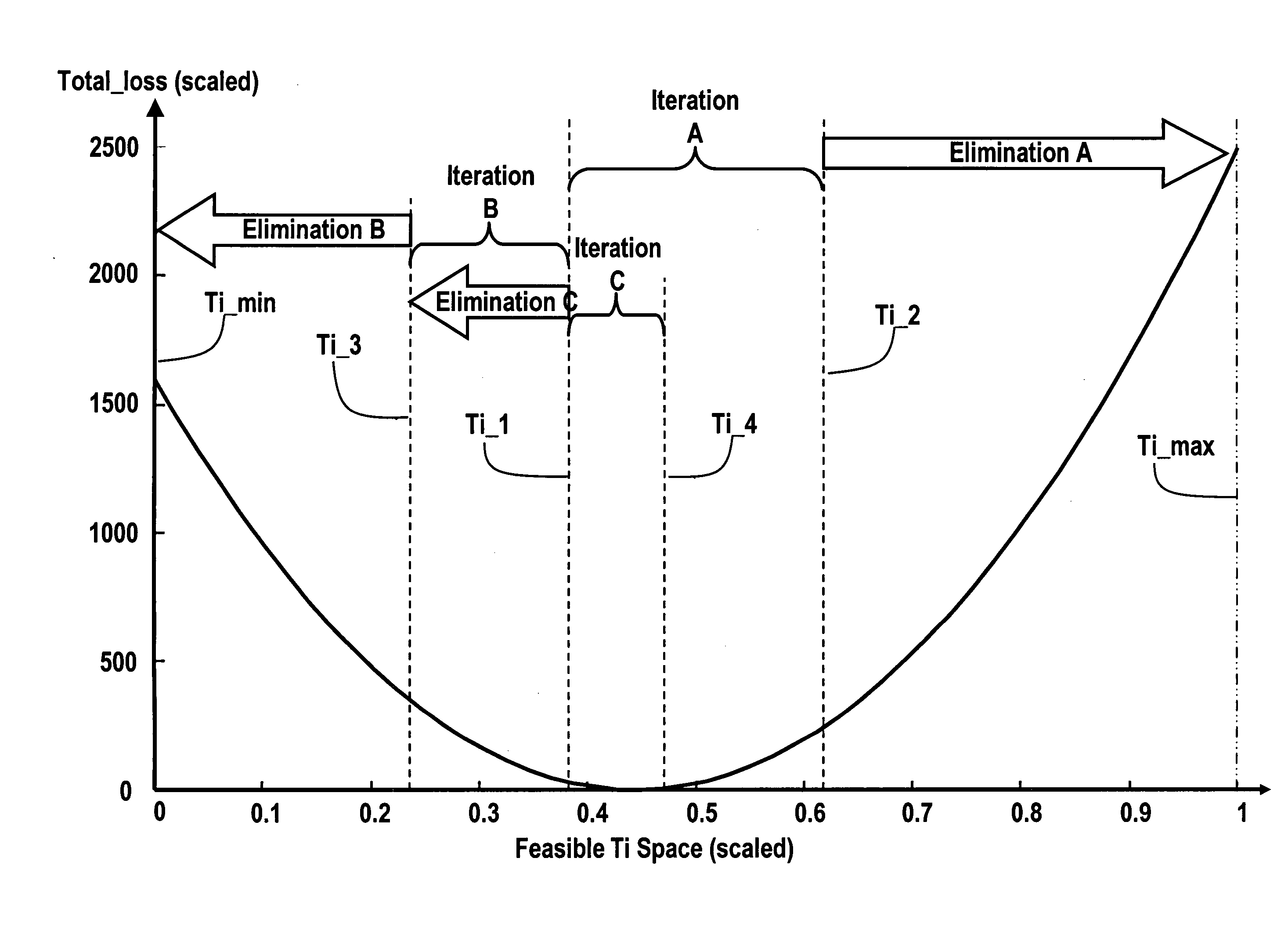
A preferred input torque for a hybrid powertrain is determined within a solution space of feasible input torques in accordance with a plurality of powertrain system constraints that results in a minimum overall powertrain system loss. System power losses and battery utilization costs are calculated at feasible input torques and a solution for the input torque corresponding to the minimum total powertrain system loss is converged upon to determine the preferred input torque.

Description

TECHNICAL FIELD The present invention is related to control of a vehicular powertrain. More particularly, the invention is concerned with a vehicle powertrain and method of determining preferred operating points for the powertrain. Most particularly, the present invention is related to a vehicle powertrain and a method of determining preferred operating points for the powertrain as a function of operating parameters of the vehicle energy storage system, such as a battery pack or array. BACKGROUND OF THE INVENTION Various hybrid powertrain architectures are known for managing the input and output torques of various prime-movers in hybrid vehicles, most commonly internal combustion engines and electric machines. Series hybrid architectures are generally characterized by an internal combustion engine driving an electric generator which in turn provides electrical power to an electric drivetrain and to a battery pack. The internal combustion engine in a series hybrid is not directly m...

Claims


Application Information

Patent Timeline
IPC IPC(8): G06F7/00G06F17/00G06F19/00
CPCB60K6/445B60W10/06B60W10/08B60W10/105Y10T477/675B60W2510/1025B60W20/102Y02T10/6286Y02T10/6239B60W30/1882B60W20/11Y02T10/84Y02T10/62
Inventor CAWTHORNE, WILLIAM R.HEAP, ANTHONY H.HUBBARD, GREGORY A.
Owner GM GLOBAL TECH OPERATIONS LLC
Why Eureka
Try Eureka