
Method of estimating floor reaction of bipedal movable body

a technology of moving body and floor reaction, which is applied in the direction of force/torque/work measurement apparatus, manufacturing tools, instruments, etc., can solve the problems of difficult to accurately grasp force sensors tend to present obstacles to the walking of human beings in the normal living environment, and the difficulty of accurately grasping etc., to achieve the effect of easy mounting, increased accuracy with which to estimate the vertical component of the floor reaction force, and high accuracy

Inactive Publication Date: 2005-04-14
HONDA MOTOR CO LTD
View PDF5 Cites 12 Cited by
  • Summary
  • Abstract
  • Description
  • Claims
  • Application Information

AI Technical Summary

Benefits of technology

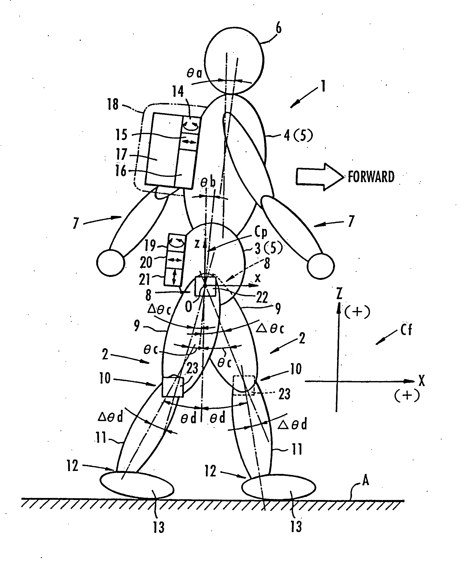
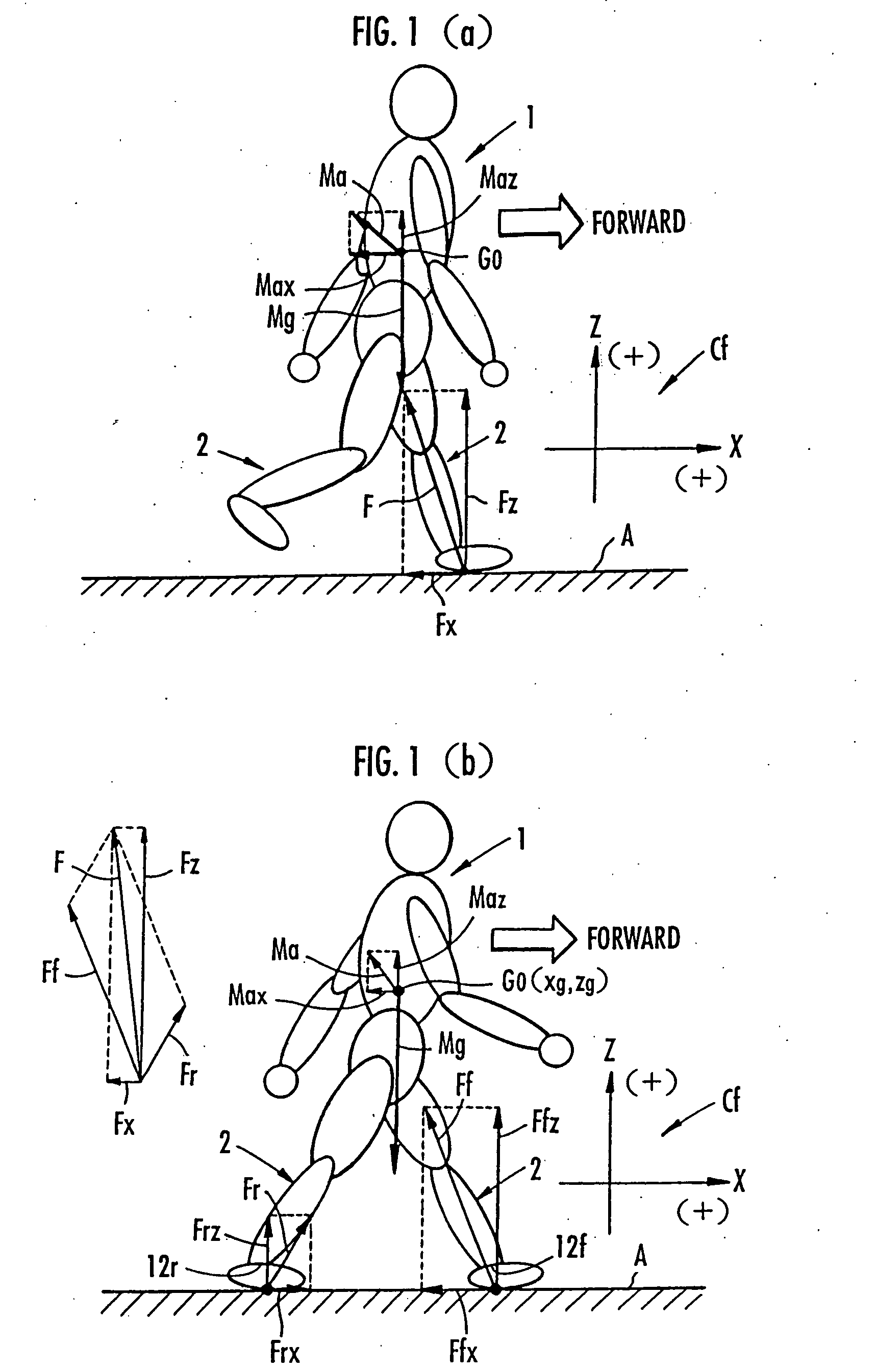
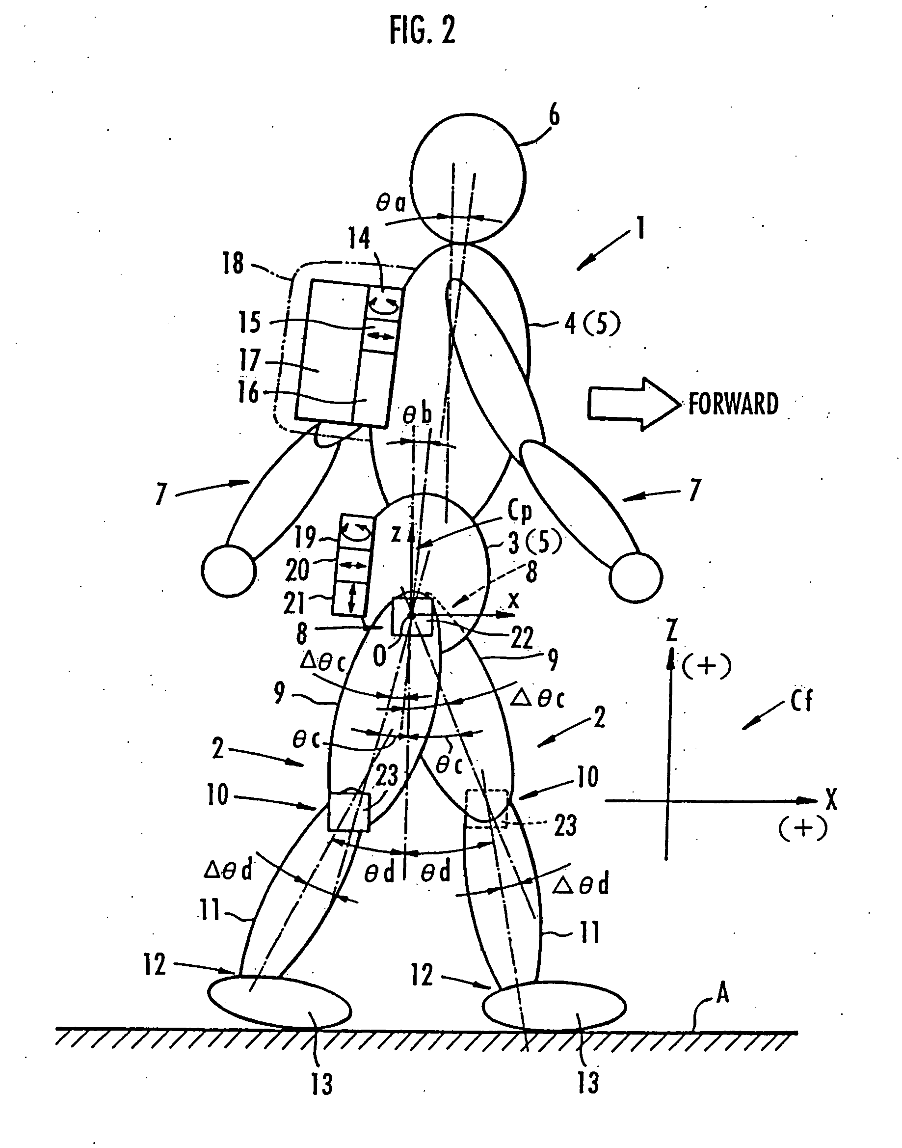
The estimated value of the total floor reaction force according to the present invention is determined according to the same process as with the prior application. The weight of the bipedal movable body which is required to determine the estimated value of the total floor reaction force may be grasped by measurements or the like. The position and acceleration of the center of gravity of the bipedal movable body can be grasped in real-time using the data of outputs from sensors which are relatively small in size and can easily be mounted on the bipedal movable body, such as sensors (potentiometers or the like) for detecting bent angles (rotational angles) of the joints of the bipedal movable body, acceleration sensors, gyrosensors, or the like. The position of the particular region of the foot from the surface of the floor can also be grasped in real-time by a simple acceleration sensor or the like for measuring inclinations which is installed on footwear or the like.
With the method of estimating a floor reaction force according to the present invention, therefore, the floor reaction force can be grasped in real-time according to a relatively simple process without the need for a force sensor mounted on an ankle or foot of the bipedal movable body or a force plate.
In the first embodiment, the particular region of the foot preferably comprises a metatarsophalangeal joint (second invention). If the particular region comprises a metatarsophalangeal joint, then the correlation between the vertical component of the floor reaction force acting on the rear leg in the two-leg supporting state and the position, from the surface of the floor, of the particular region (metatarsophalangeal joint) of the foot of the front leg is highly increased. Therefore, the accuracy with which to estimate the vertical component of the floor reaction force is increased.

Problems solved by technology

According to the above process, since the floor reaction force on each leg is grasped for one step or a plurality of steps of the bipedal movable body, it is difficult to grasp the floor reaction force accurately if the gait of the bipedal movable body changes sequentially.
Therefore, it is difficult to grasp the floor reaction force accurately by reducing the effect of the environment in which the bipedal movable body moves and the difference between individual units of the bipedal movable body.
If floor reaction forces on the legs of a human being are to be recognized based on output signals from force sensors, then since the force sensors need to be mounted on the ankles and feet of the human being, the force sensors tend to present an obstacle to the walking of the human being in the normal living environment.
Use of the force plate is only effective to grasp the floor reaction plate only in the environment in which the force plate is used.
It has been found that the estimated values of the vertical components Ffz, Frz of the floor reaction forces on the legs in the two-leg supporting state, which are determined by the method of the prior application are not necessarily of satisfactory accuracy.
The estimated values of the vertical components of the floor reaction forces which become large under the influence of the weight of the bipedal movable body 1 tend to suffer a larger error than their components in the direction of travel.

Method used


Image

  • Method of estimating floor reaction of bipedal movable body
  • Method of estimating floor reaction of bipedal movable body
  • Method of estimating floor reaction of bipedal movable body

Examples


second embodiment

A second embodiment for determining estimated values of the components Ffx, Frx in the direction of travel of the floor reaction force acting on the legs 2 according to the above process will be described below. as shown in FIG. 12, the processing device 16 has, in place of the ankle position calculating means 32 according to the first embodiment, a timing means 42 for measuring an elapsed time from the start of the two-leg supporting state each time the start of the two-leg supporting state (the end of the one-leg supporting state) is grasped by the leg motion determining means 25, a traveling speed estimating means 43 for estimating a traveling speed of the human being 1 using the data of the respective tilted angle θc, θd of the thigh 9 and the lower thigh 11 of each leg 2 from the leg posture calculating means 29 and the timing data from the timing means 42 each time the start of the two-leg supporting state (the end of the one-leg supporting state) is grasped by the leg motion...


PUM

PropertyMeasurementUnit
reaction forceaaaaaaaaaa
forceaaaaaaaaaa
gravityaaaaaaaaaa

Abstract

It is determined whether the motion state of legs 2, 2 is a one-leg supporting state or a two-leg supporting state, and a total floor reaction force is estimated based on a motion equation of the center of gravity of a bipedal movable body 1. If the motion state of legs 2, 2 is the one-leg supporting state, the estimated value of the total floor reaction force is used as an estimated value of the floor reaction force on the leg 2 which is landed. When the motion state changes to the two-leg supporting state, a vertical component of the floor reaction force on the rear leg is estimated from the MP height of the front leg based on a predetermined correlation between the MP height of the front leg and the vertical component of the floor reaction force on the leg.

Description

TECHNICAL FIELD The present invention relates to a method of estimating the vertical component of a floor reaction force acting on each leg of a bipedal movable body such as a human being, a bipedal walking robot, or the like, particularly while the bipedal movable body is in a two-leg supporting state in which both legs of the bipedal movable body are landed on the floor. BACKGROUND ART For controlling the operation of a walking assisting device for assisting a human being to walk or the movement of a bipedal walking robot, it is necessary to sequentially grasp a floor reaction force acting on a leg of the human being or the bipedal walking robot (specifically, a force acting on the landing area of the leg from the floor). Grasping the floor reaction force makes it possible to grasp a moment or the like that acts on joints of the leg of the bipedal movable body, and also to determine a desired assistive force for the walking assisting device or a desired drive torque for each joi...

Claims


Application Information

Patent Timeline
Patent Type & Authority Applications(United States)
IPC IPC(8): G01L5/00B25J5/00B25J13/08B62D57/032
CPCB25J13/085B62D57/032B25J13/088
Inventor KAWAI, MASAKAZUIKEUCHI, YASUSHI
Owner HONDA MOTOR CO LTD
Learn More