Creel for textile machines

Inactive Publication Date: 2005-04-21
SAURE GMBH & CO KG
View PDF7 Cites 8 Cited by
  • Summary
  • Abstract
  • Description
  • Claims
  • Application Information

AI Technical Summary

Benefits of technology

[0006] The invention offers a solution to the challenge of providing a creel that is configured such that the creel, relative to the creel described in DE-AS 1 145 527, comprises a simplifi

Problems solved by technology

In addition to the relatively expensive control mechanism associated therewith, this known package holder suffers from the significant disadvantage that the insert pegs must be mounted on the package holder in a l

Method used


Image

  • Creel for textile machines
  • Creel for textile machines
  • Creel for textile machines

Examples


Embodiment Construction

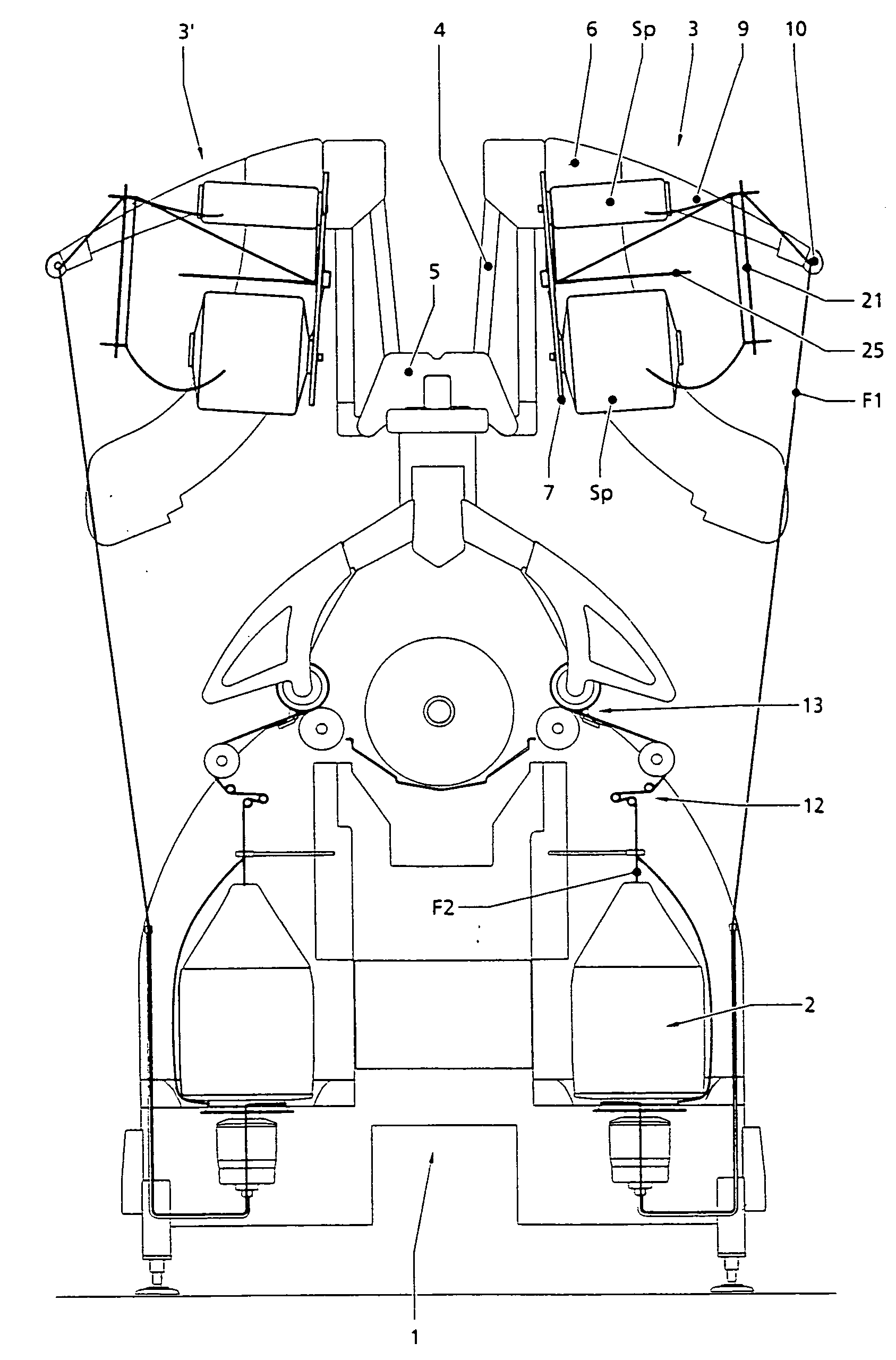
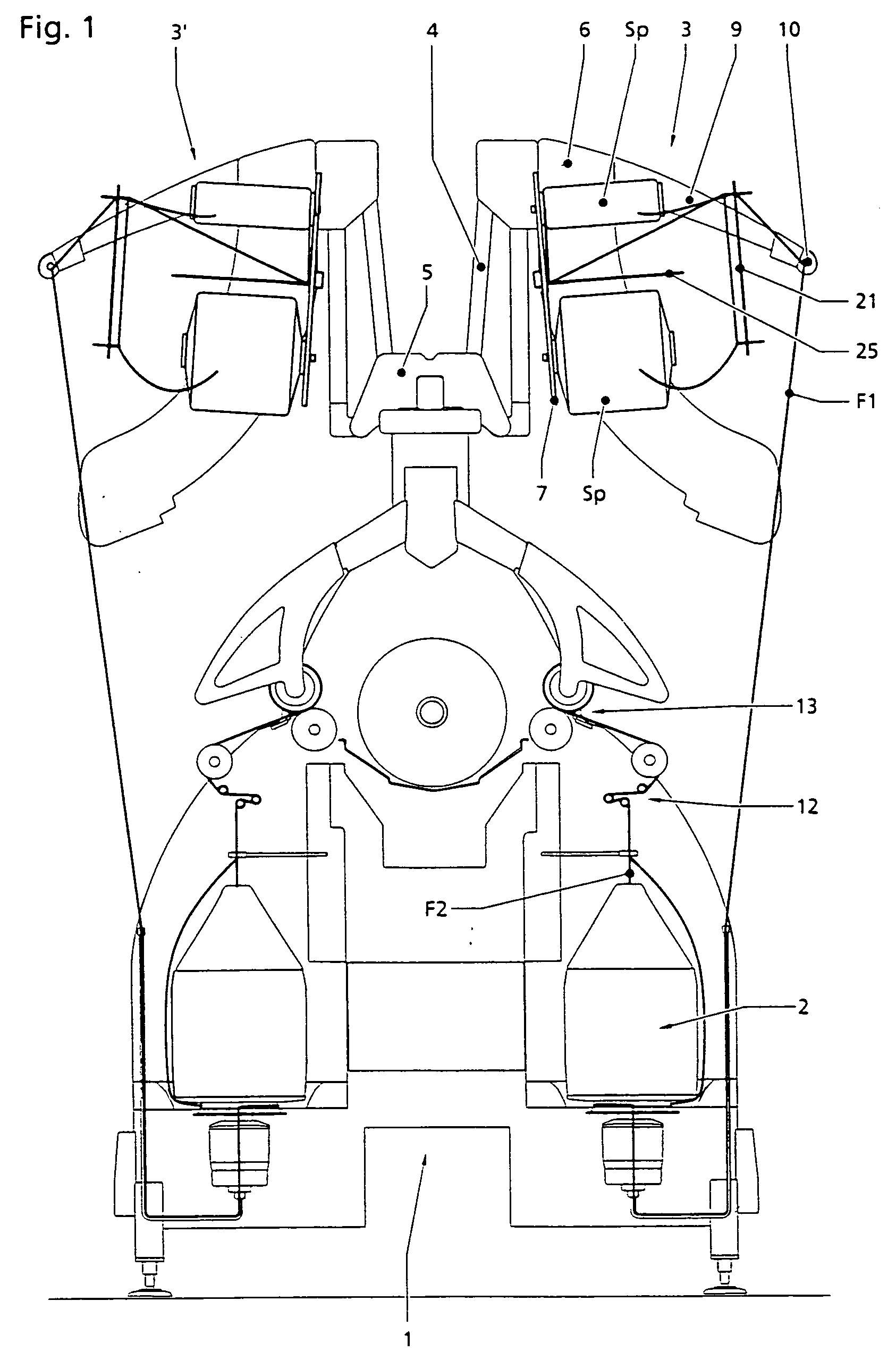
[0022] In connection with the textile machine 1 that is only schematically illustrated in FIG. 1, the textile machine is, for example, a cabling machine having cable spindles extending on both sides thereof along the machine longitudinal direction. The one creel 3 associated with an individual cable spindle 2 is pivotally mounted on the upper side of the machine frame 5 by means, for example, of a four piece linkage 4. The individual creel 3 can also be configured in a conventional manner as a double creel such that each creel is provided with four feed packages Sp or, respectively, can be loaded with such feed packages, so that each respective pair of neighboring cable spindles of the cabling machine can be served by an individual package creel. In connection with the feed package Sp, such packages are the so-called simple-feed packages for the outer yarn of the cabling process.

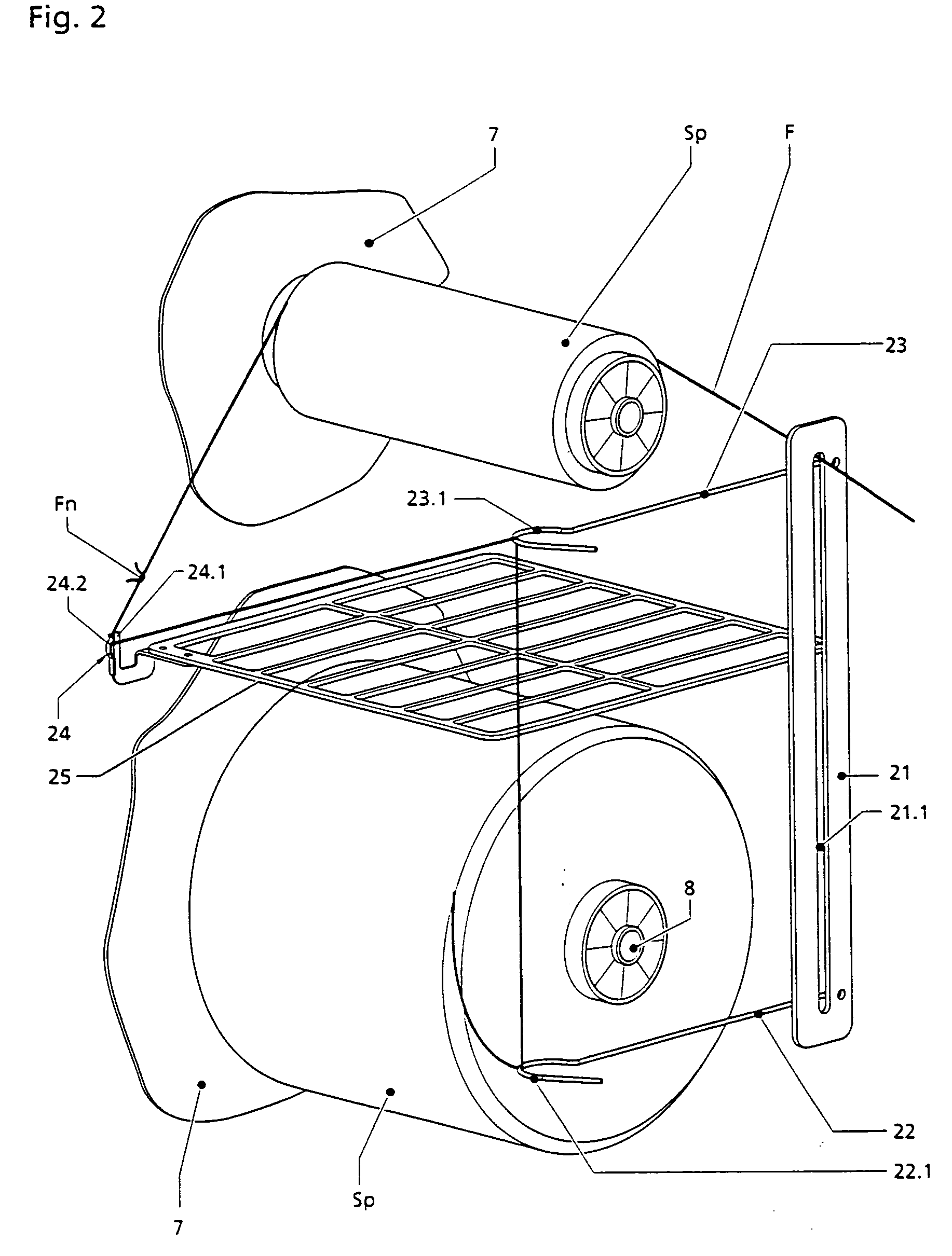
[0023] The creel 3 comprises a support plate 6 on which, on each side thereof, there is respectively mou...


PUM


Abstract

A creel is provided with two insert pegs that are mounted on a retainer secured to a machine frame that is pivotable between a lower loading station and an upper loading position. The creel also includes a yarn guide element with a longitudinal opening whose length substantially corresponds to the vertical spacing between the axes of the insert pegs such that the ends of the longitudinal opening can be brought into a position lying substantially on the extension of the insert peg axes. Two elongate guide organs are mounted on the side of the yarn guide element and each has a yarn eye opening. The creel further includes a yarn retaining organ located between the insert pegs at a lateral spacing from the plane defined by the insert peg axes and whose retaining force lies under the withdrawal force by which the yarn is drawn off a feed package.

Description

BACKGROUND OF THE INVENTION [0001] The invention relates to a creel with at least two insert pegs arranged one above the other that are mounted on a retainer secured to a machine frame that is pivotable between a lower loading station and an upper loading position. A creel of this type is described, for example, in FR-A-2 794 136. [0002] On creels of this type, fully wound feed packages are inserted on respective insert pegs, the feed packages having a yarn reserve so that, after the running out of yarn from the first package, the drawing of yarn from the second package occurs, whereby the yarn end of a first package is connected with the beginning portion of the yarn of a second package. [0003] A package holder described in DE-AS 1 145 527 is so conceived that, upon rewinding of yarn after the run out of yarn of an unwinding package, an operational stoppage is to be avoided as a consequence of the run out process being configured to be continuous, in that the yarn end of the unwind...

Claims


Application Information

Patent Timeline
IPC IPC(8): B65H49/12B65H49/00B65H57/18D01H1/18D01H13/04
CPCD01H13/04D01H1/18
Inventor BECKMANN, MARKUSSCHWARZER, RAINERTETZLAFF, GEORG
Owner SAURE GMBH & CO KG
Why Eureka
Try Eureka