Al technical title is built by PatSnap Al team. It summarizes the technical point description of the patent document.
a technology of infrared camera and thermal imaging, which is applied in the field of thermal imaging, can solve the problems of high cost of “focal plane” technology, out of reach for the vast majority of commercial and consumer markets, and driving costs up
Inactive Publication Date: 2005-04-21
REDSHIFT SYST CORP
View PDF75 Cites 129 Cited by
Summary
Abstract
Description
Claims
Application Information
AI Technical Summary
This helps you quickly interpret patents by identifying the three key elements:
Problems solved by technology
Method used
Benefits of technology
[0015] Each pixel element of the array of thermally-tunable optical filter pixel elements includes an index tunable thin film interference coating, which forms a single-cavity or multiple-cavity Fabry-Pero
Problems solved by technology
However, all of these “focal plane” technologies are expensive (for example, the lowest-priced cameras are just breaking the $10,000 barrier), making thermal imaging out of reach for the vast majority of the commercial and consumer market
Method used
Image
Click on the blue label to locate the original text in one second.
Reading with bidirectional positioning of images and text.
Examples
Embodiment Construction
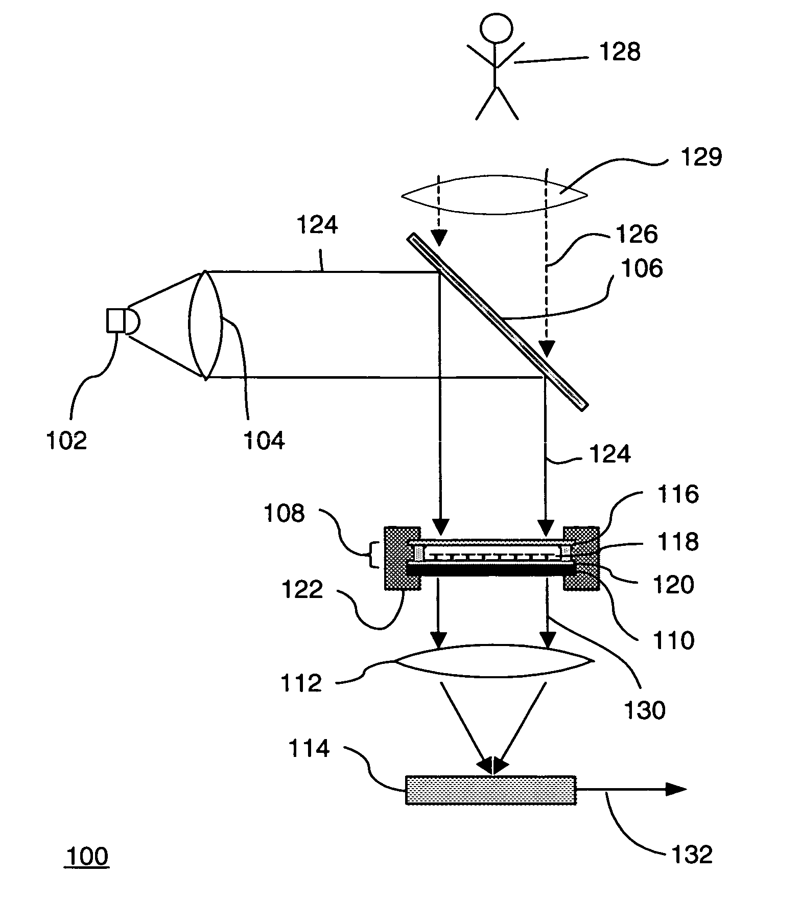
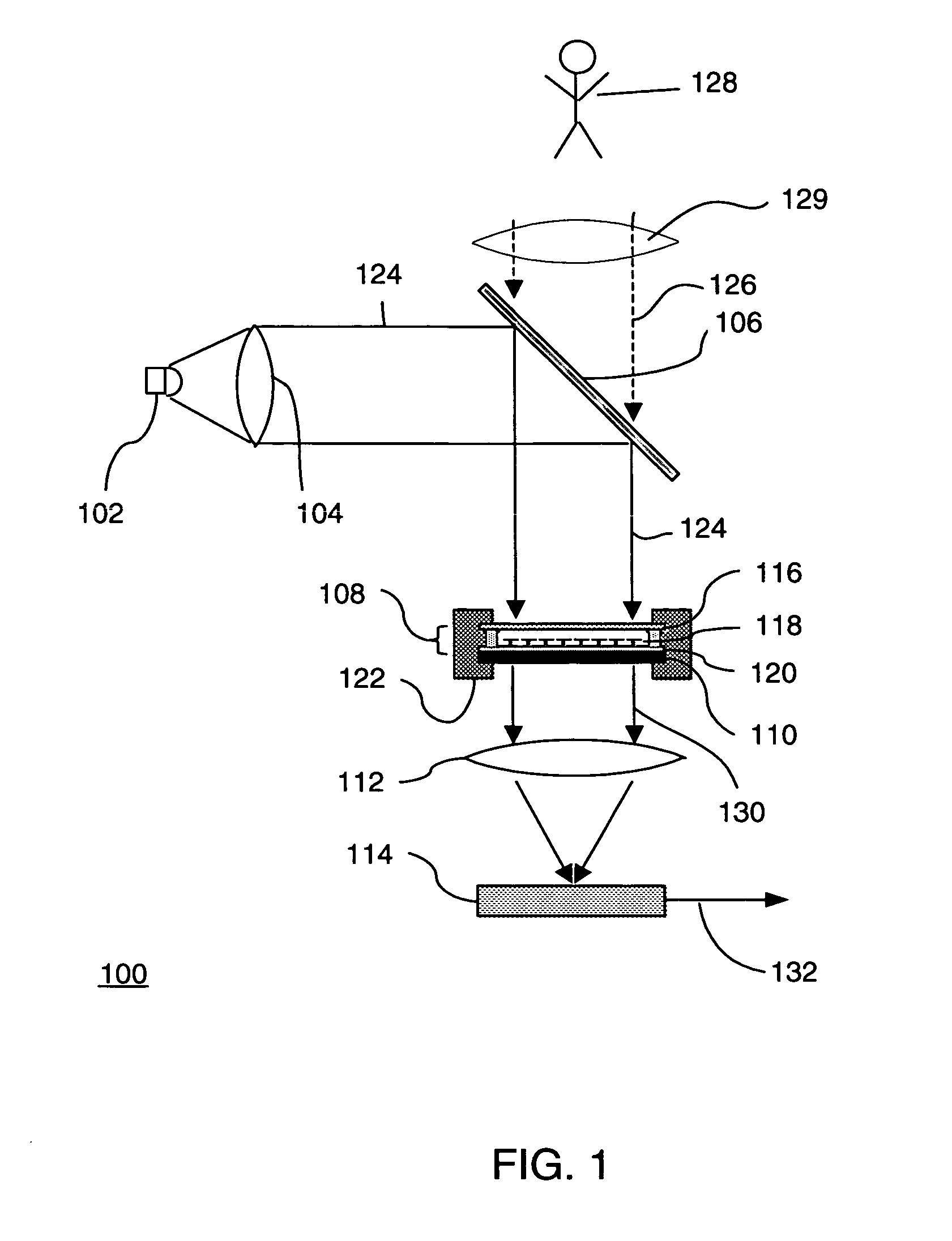
[0041] The described embodiment is an uncooled, infrared (IR) camera system that uses thermally-tunable optical filter elements that respond to IR energy (e.g., light with wavelength typically ranging from 8 to 15 μm, although other wavelengths may be considered IR—also referred to herein as IR light and IR radiation) radiated by a scene to be imaged. The filter elements modulate a near-IR (NIR) carrier signal (e.g., light with a wavelength of approximately 850 nm—also referred to as NIR optical signal, NIR light, probe, probe signal or probe light) as a result of changes in the IR energy. The camera system detects the modulated carrier signal with a NIR detector (e.g., a CMOS or CCD based imaging array, or a p-i-n photo diode array).
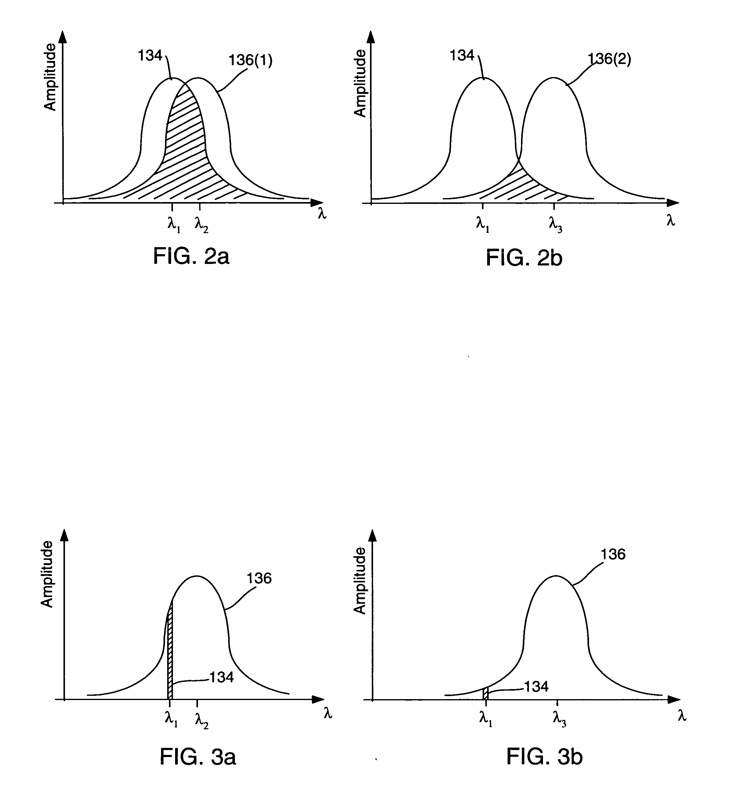
[0042] The IR camera system is based on a thermal sensor that uses optical readout. The underlying principle of this thermal sensor described herein is simple. A narrowband source generates an “optical carrier signal” with a specific wavelength spectru...
PUM
Abstract
An IR camera system includes an array of thermally-tunable optical filter pixels, an NIR source and an NIR detector array. The IR camera system further includes IR optics for directing IR radiation from a scene to be imaged onto the array of thermally-tunable optical filter pixels and NIR optics for directing NIR light from the NIR source, to the filter pixels and to the NIR detector arrays. The NIR source directs NIR light onto the array of thermally-tunable optical filter pixels. The NIR detector array receives NIR light modified by the array of thermally-tunable optical filter pixels and for produces an electrical signal corresponding to the NIR light the NIR detector array receives.
Description
CROSS-REFERENCE TO RELATED APPLICATIONS [0001] This application claims benefit of the following Patent Applications: [0002] U.S. Provisional Patent Application Ser. No. 60 / 498,167, filed Aug. 26, 2003; [0003] U.S. Provisional Patent Application Ser. No. 60 / 566,610, filed Apr. 28, 2004; [0004] U.S. Provisional Patent Application Ser. No. 60 / 506,985, filed Sept. 29, 2003; [0005] U.S. Provisional Patent Application Ser. No. 60 / 535,389, filed Jan. 9, 2004; [0006] U.S. Provisional Patent Application Ser. No. 60 / 535,391, filed Jan. 9, 2004; [0007] U.S. Provisional Patent Application Ser. No. 60 / 583,573, filed Jun. 28, 2004; and, [0008] U.S. Provisional Patent Application Ser. No. 60 / 583,341, filed Jun. 28, 2004.TECHNICAL FIELD [0009] This invention relates generally to thermal imagers. BACKGROUND [0010] The market for infrared cameras is large, and growing quickly, driven by military, security, medical, construction and automotive markets. Of particular interest are the wavelengths betwee...
Claims
Application Information
Patent Timeline
Application Date:The date an application was filed.
Publication Date:The date a patent or application was officially published.
First Publication Date:The earliest publication date of a patent with the same application number.
Issue Date:Publication date of the patent grant document.
PCT Entry Date:The Entry date of PCT National Phase.
Estimated Expiry Date:The statutory expiry date of a patent right according to the Patent Law, and it is the longest term of protection that the patent right can achieve without the termination of the patent right due to other reasons(Term extension factor has been taken into account ).
Invalid Date:Actual expiry date is based on effective date or publication date of legal transaction data of invalid patent.