Electro-mechanical actuator braking apparatus and method using motor commutation sensor output to derive piston displacement

a technology of electromechanical actuators and braking apparatuses, which is applied in the direction of motor/generator/converter stoppers, dynamo-electric converter control, instruments, etc., can solve the problems of reducing the reliability of the system, increasing the cost, weight and size of the ema arrangement, and reducing the use of dedicated position sensors

Active Publication Date: 2005-04-21
HONEYWELL INT INC
View PDF28 Cites 60 Cited by
  • Summary
  • Abstract
  • Description
  • Claims
  • Application Information

AI Technical Summary

Benefits of technology

[0009] An additional aspect of the invention comprises a method of controlling an electric brake that involves providing a brake disk stack and an electromagnetic actuator having a motor comprising a rotor, a stator and a commutation sensor producing an output. An analog/digital converter operatively connected to the commutation sensor produces a commutation signal that varies from zero to a maximum value over a commutation sensor period and has zero crossings. A motor controller is provided that generates a control signal based on the commutation signal for controlling the motor. A processor is operatively connected to an accumulator storing a value and to a memory. The method further involves moving the ram until the first stop surface engages a stop, storing a first value of the commutation signal in the memory when the first stop surface engage

Problems solved by technology

The inventor of this application has found, however, that the use of a dedicated position sensor in an EMA arrangement has certain drawb

Method used


Image

  • Electro-mechanical actuator braking apparatus and method using motor commutation sensor output to derive piston displacement
  • Electro-mechanical actuator braking apparatus and method using motor commutation sensor output to derive piston displacement
  • Electro-mechanical actuator braking apparatus and method using motor commutation sensor output to derive piston displacement

Examples


Embodiment Construction

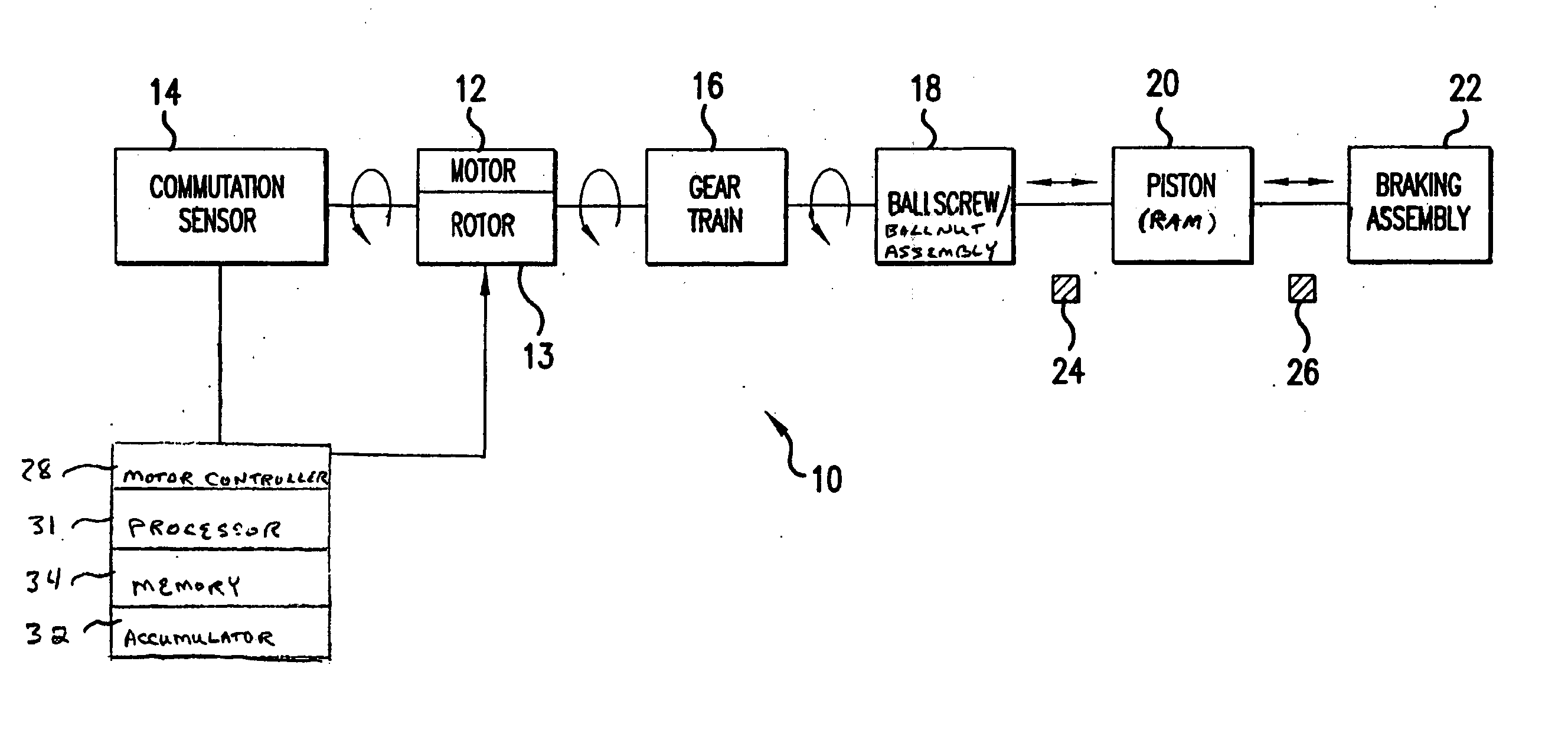
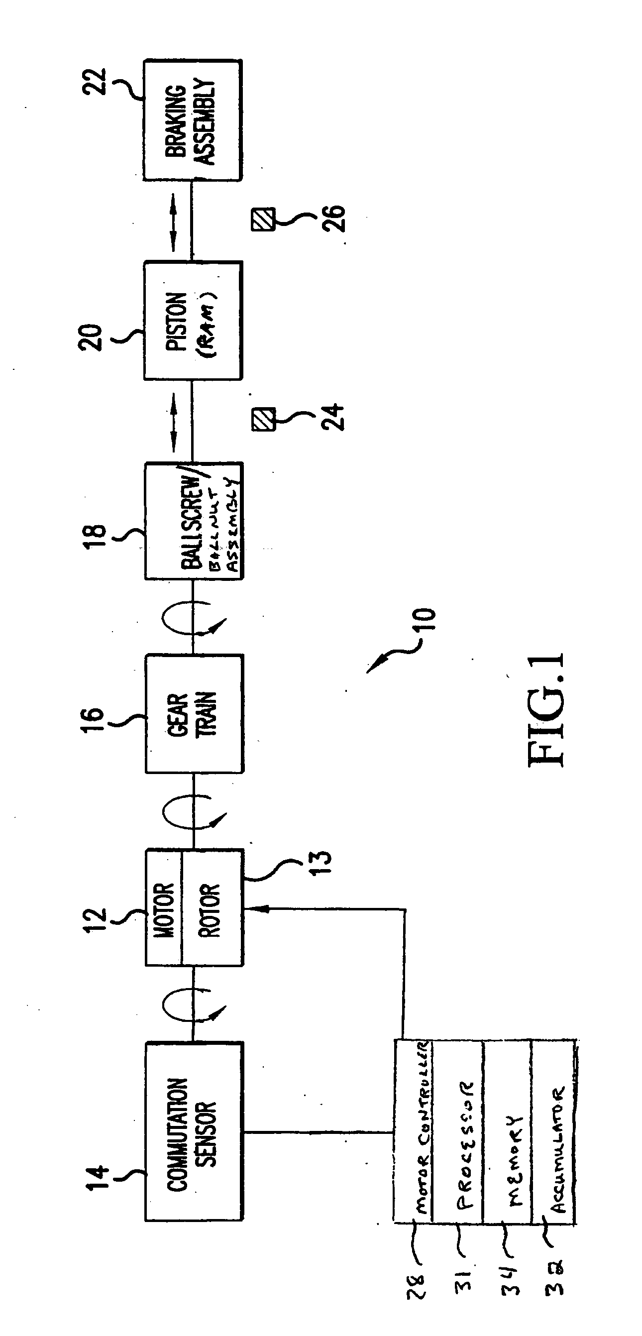
[0016] Referring now to the drawings, wherein the showings are for the purpose of illustrating preferred embodiments of the invention only and not for the purpose of limiting same, FIG. 1 illustrates an electromechanical actuator (EMA) braking arrangement 10 in accordance with an embodiment of the present invention. As shown in FIG. 1, the EMA braking arrangement 10 of this embodiment includes a brushless motor 12 having a rotor 13 and a commutation sensor 14; a reduction geartrain 16 connected to the motor 12 to amplify torque; a ballscrew / ballnut assembly 18 for translating rotary motion from the geartrain 16 to linear motion; a piston (sometimes referred to as a “ram”) 20 connected to the ballscrew / ballnut assembly 18 to provide output force and motion; and a braking assembly 22 actuated by the force of ram 20 thereagainst. The EMA braking arrangement 10 of FIG. 1 further includes internal mechanical stops 24 (“retract stop”) and 26 (“extend stop”) and a motor controller 28 that ...


PUM


Abstract

A braking system is disclosed that includes a brake (22), a ram (20) shiftable in a linear direction relative to the brake (22) for actuating the brake (22), and a stop (24) for limiting movement of the ram (20). The system further includes a motor (12) for moving the ram (20) which motor (12) includes a stator and a rotor (13) and a commutation sensor (14) producing an output. A motor controller (28) receives a commutation signal based on the output and controls the motor (12) based on the commutation signal. A processor (31) also uses the commutation signal to generate a position signal indicative of the position of the ram (20) relative to the stop (24). Methods of using this system are also disclosed.

Description

CROSS-REFERENCE TO RELATED APPLICATIONS [0001] This application claims the benefit of U.S. Provisional Patent Application No. 60 / 511,108 filed Oct. 15, 2003, the entire contents of which are hereby incorporated by reference.FIELD OF THE INVENTION [0002] This invention relates to braking systems utilizing electro-mechanical actuators, and more particularly, to a braking system and method using motor commutation sensor output to determine the position of an electro-mechanical actuator piston. BACKGROUND OF THE INVENTION [0003] Braking systems using electro-mechanical actuators (EMAs) have been considered as alternatives to conventional hydraulic braking arrangements. In one previously disclosed aircraft braking arrangement using EMAs, a plurality of EMAs are mounted on a brake carrier housing in an annular pattern about the axis of wheel rotation. The brake carrier housing is fixed to a torque tube having stator disks of a brake disk stack attached thereto. Rotor disks of the brake di...

Claims


Application Information

Patent Timeline
IPC IPC(8): B60T8/17B60T13/74B60T17/22F16D65/14F16D66/00G01B7/02G01D5/245
CPCF16D2066/003B60T8/1703
Inventor ETHER, RUSS
Owner HONEYWELL INT INC
Why Eureka
Try Eureka