Non-reciprocal element with three central conductors and communication apparatus using the same
- Summary
- Abstract
- Description
- Claims
- Application Information
AI Technical Summary
Benefits of technology
Problems solved by technology
Method used
Image

Examples
first embodiment
[1] First Embodiment
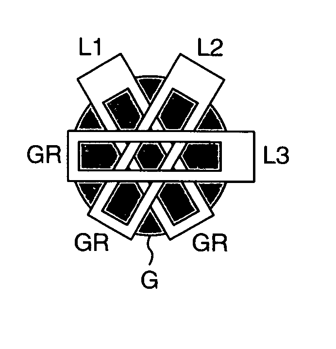
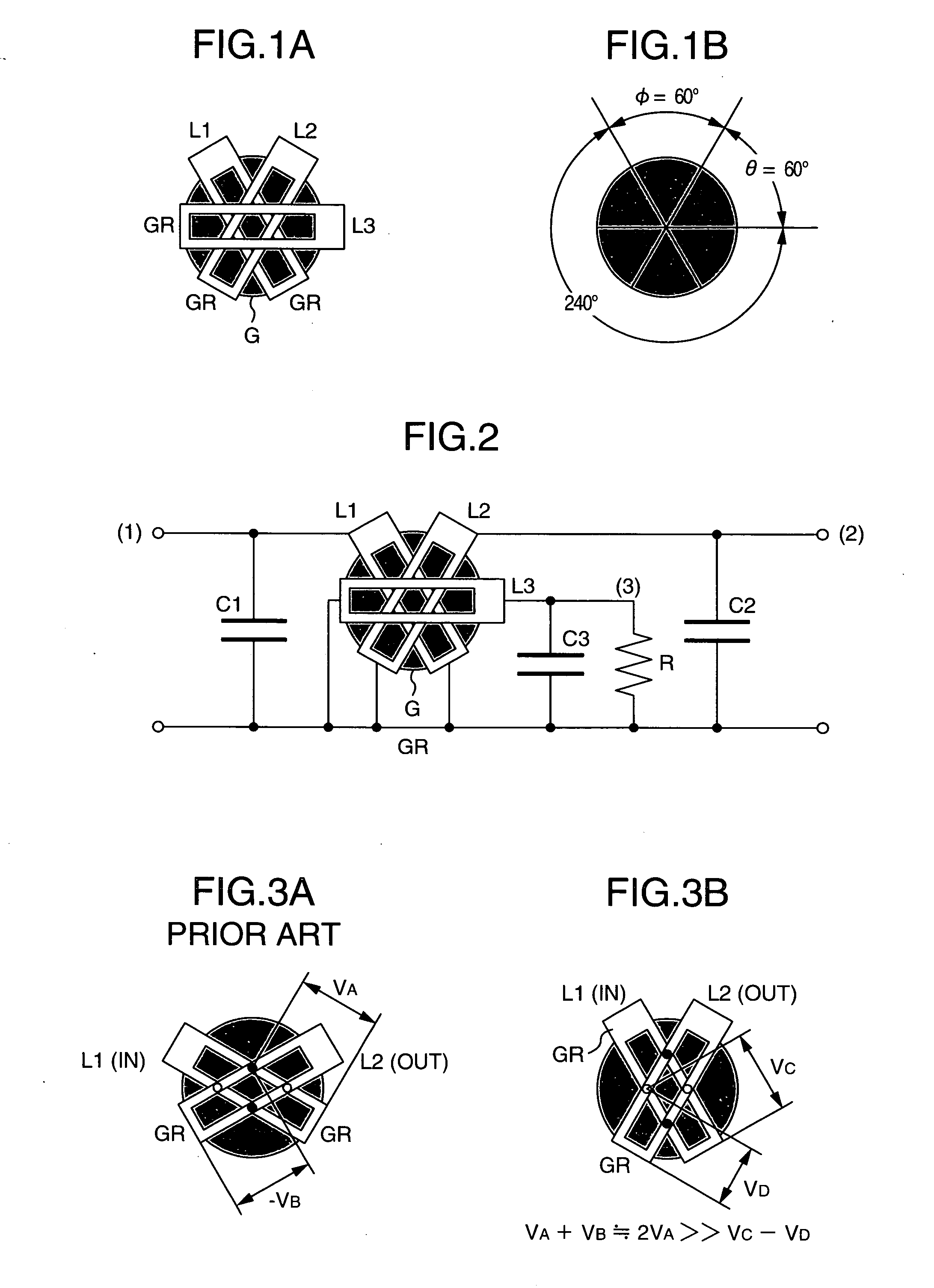
[0038]FIGS. 1A, 1B are assembly diagrams showing central conductors and a ferrite thin plate according to an embodiment of the invention. First, second and third central conductors L1, L2, L3 crossed and electrically insulated with each other are arranged on the disk-like ferrite thin plate G. The difference of this embodiment from the prior art lies in that the intersection angle φ between the first and second central conductors is not 120 degrees but 60 degrees. The intersection angle is defined as the angle between the center lines of the central conductors crossing the ferrite thin plate as viewed from the input / output terminal. In similar fashion, the intersection angle θ between the second and third central conductors is 60 degrees. The inventor has found that this configuration remarkably improves the insertion loss and the isolation bandwidth. The electrical insulation, though not shown, can be achieved by inserting Teflon or polyimide adhesive tape betwe...
second embodiment
[2] Second Embodiment
[0049]FIGS. 7A and 7B show another embodiment of the invention. This embodiment represents a case in which the intersection angle φ between the first central conductor L1 and the second central conductor L2 is 40 degrees, and the intersection angle θ between the second central conductor L2 and the third central conductor L3 is also 40 degrees. Both angles are smaller than 60 degrees.
third embodiment
[3] Third Embodiment
[0050]FIGS. 8A and 8B show still another embodiment of the invention, in which the intersection angle φ between the first central conductor L1 and the second central conductor L2 is 40 degrees, and the intersection angle θ between the second central conductor L2 and the third central conductor L3 is 70 degrees. In this case, 70 degrees is selected as one half of the supplementary angle of 40 degrees. Also, the interval between the two conductor lines of the third central conductor L3 is wider. This is designed to prevent the central portion of the third central conductor from being superposed on the other central conductors when the former is bent and laid and thus to keep a low real height of the isolator. By doing so, the impedance of the central conductor L3 naturally changes, and therefore the value of the resistor R connected also requires a corresponding adjustment.
PUM
 Abstract
Description
Claims
Application Information
 - Generate Ideas
- Intellectual Property
- Life Sciences
- Materials
- Tech Scout
- Unparalleled Data Quality
- Higher Quality Content
- 60% Fewer Hallucinations
Browse by: Latest US Patents, China's latest patents, Technical Efficacy Thesaurus, Application Domain, Technology Topic, Popular Technical Reports.
© 2025 PatSnap. All rights reserved.Legal|Privacy policy|Modern Slavery Act Transparency Statement|Sitemap|About US| Contact US: help@patsnap.com