

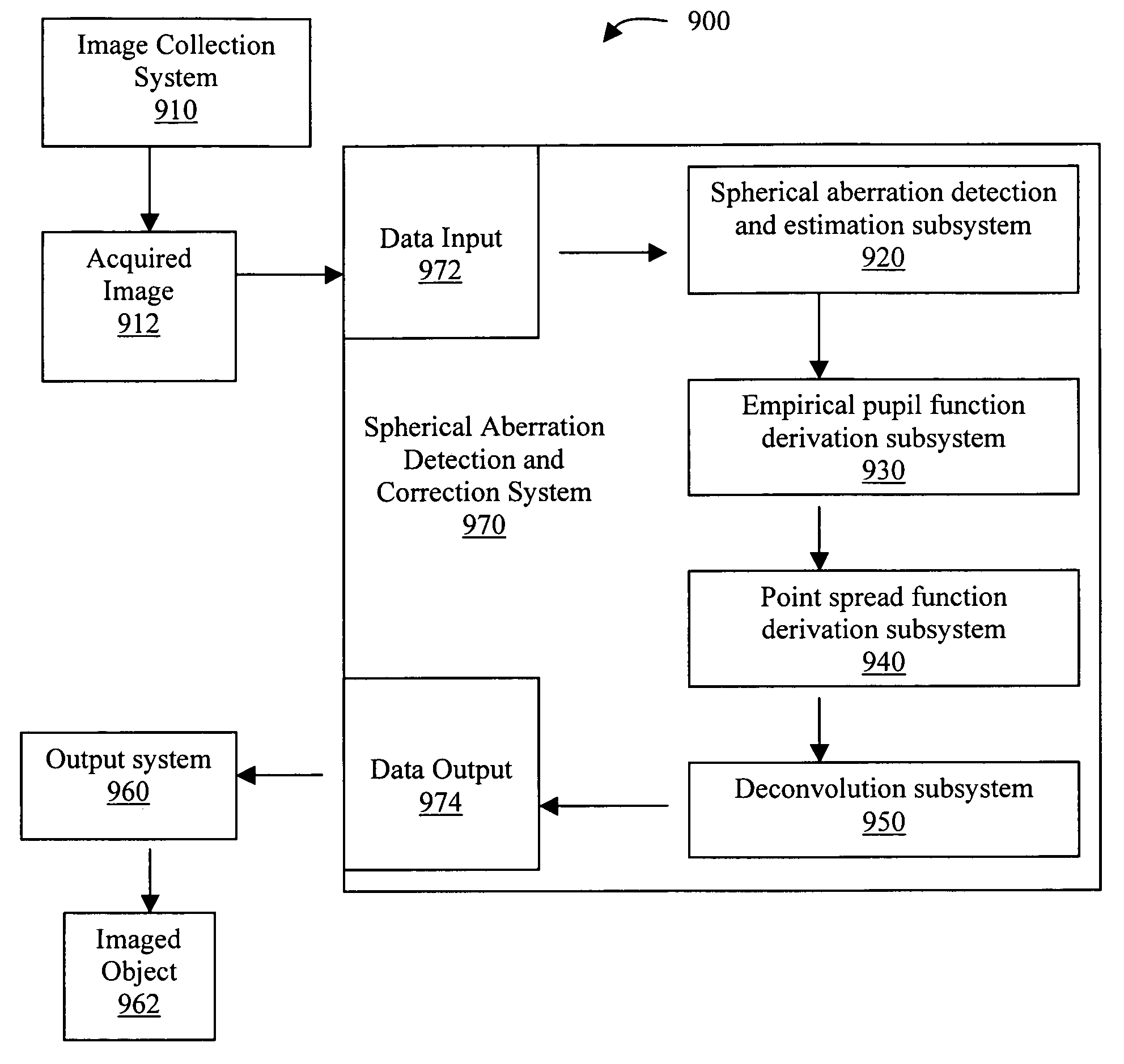
Methods, system, and program product for the detection and correction of spherical aberration
a technology of spherical aberration and program products, applied in the field of optical systems, can solve the problems of spherical aberration not being detected, spherical aberration being more problematic in spherical lenses, and common problems such as spherical aberration,
- Summary
- Abstract
- Description
- Claims
- Application Information
AI Technical Summary
Benefits of technology
Problems solved by technology
Method used
Image

Examples
Embodiment Construction
A. Spherical Aberration Detection
[0053] As noted above, users of microscopy systems are often unaware of the presence of spherical aberration during the collection of image data and may sometimes remain unaware that the data are so affected. Accordingly, one objective of the present invention is the detection of spherical aberration in image data.
[0054] Two novel methods for detecting spherical aberration are provided. The first is a correlation-based method. The second is an energy minimization method.
[0055] The correlation-based method is predicated on the fact that if a spherically aberrated point spread function (PSF) is generated correctly and approximately the same as the true PSF, then similar structures are likely to be observed both in the spherically aberrated image data and in the reconstructed PSF. Therefore, the correlation-based method of the present invention first requires the generation of a plurality of spherically aberrated PSFs, each empl...
PUM
 Abstract
Description
Claims
Application Information