Sliding adjuster

a technology of adjuster and headlamp, which is applied in the direction of lighting and heating apparatus, instruments, lighting support devices, etc., can solve the problems that the method of adjusting sealed beam lamps cannot be used to adjust reflectors, and the device cannot be effectively used in vehicles. achieve the effect of precise adjustment control and cost effectiv

Inactive Publication Date: 2005-04-21
BURTON TECH
View PDF32 Cites 5 Cited by
  • Summary
  • Abstract
  • Description
  • Claims
  • Application Information

AI Technical Summary

Benefits of technology

[0006] The present invention relates to a sliding headlamp adjuster that allows for precise adjustment control, can be used where the area above and behind the lamp assembly is inaccessible, ensures smooth operation, can include a vehicle headlamp aiming device (“VHAD”), i...

Problems solved by technology

Thus, the constraints of the installation area and the demands of the automobile manufacturers for aerodynamic headlamp designs dictate the location from which adjustment must be made.
Accordingly, such devices cannot be effectively used in vehicles where the area immediately behind and above the lamp assembly is not accessible.
Thus, existi...

Method used


Image

  • Sliding adjuster
  • Sliding adjuster
  • Sliding adjuster

Examples


Embodiment Construction

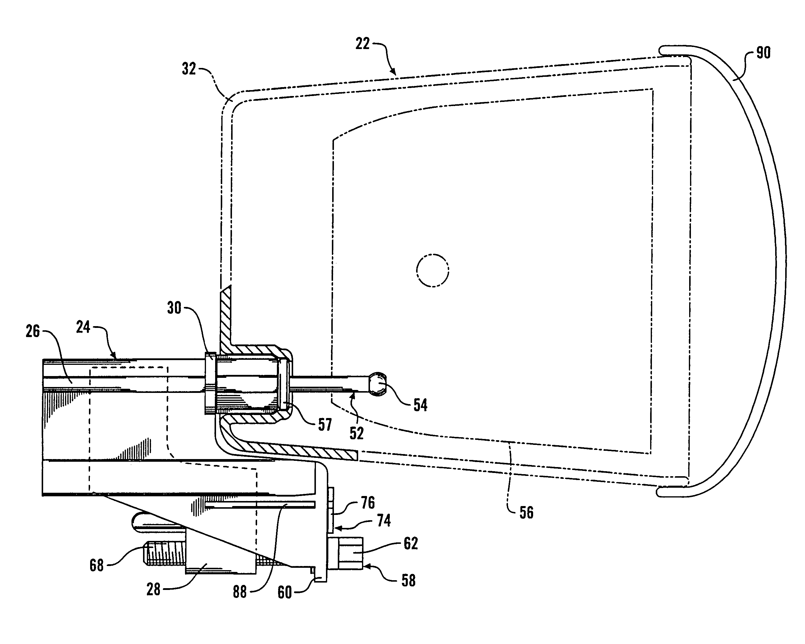
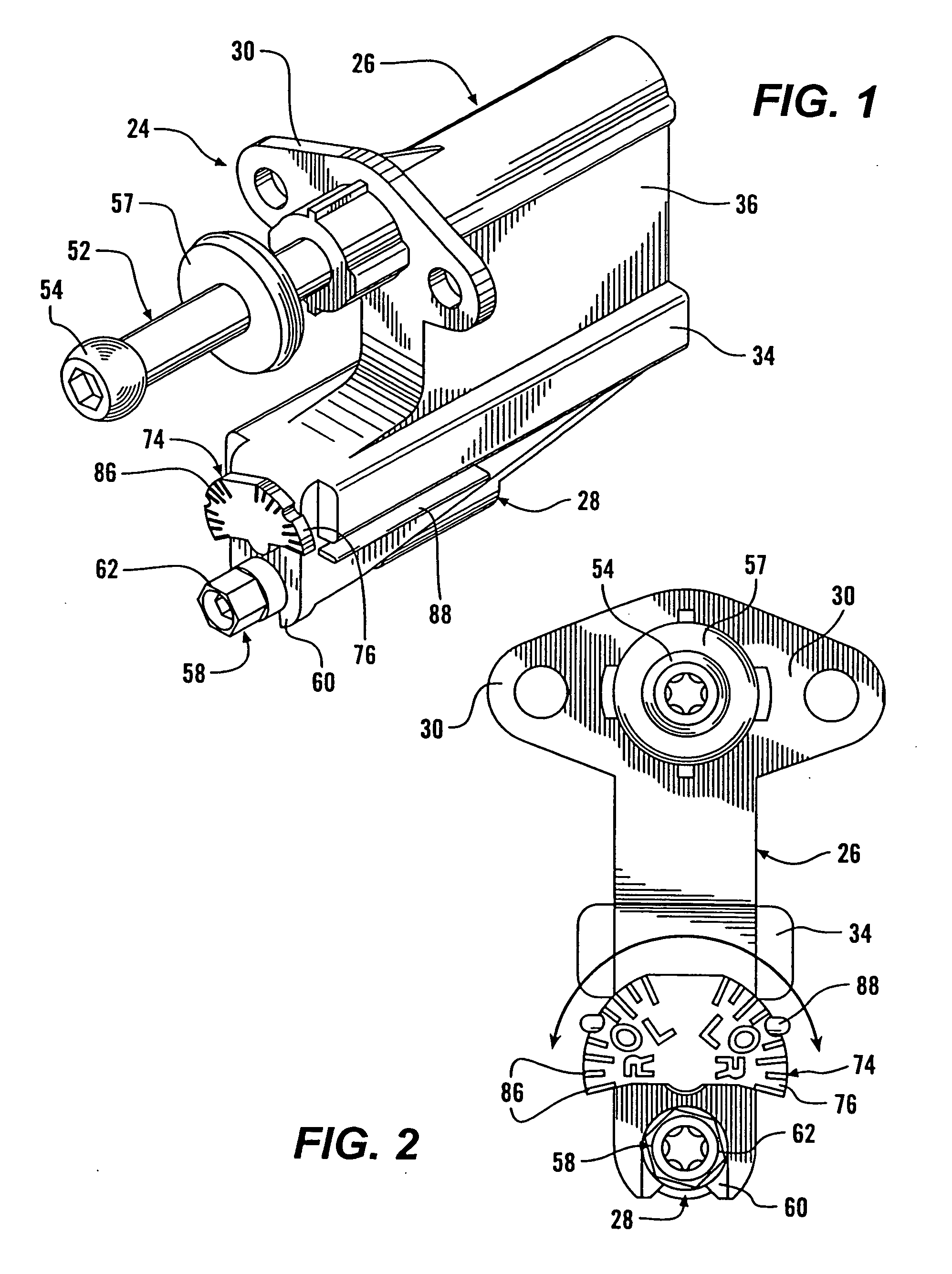
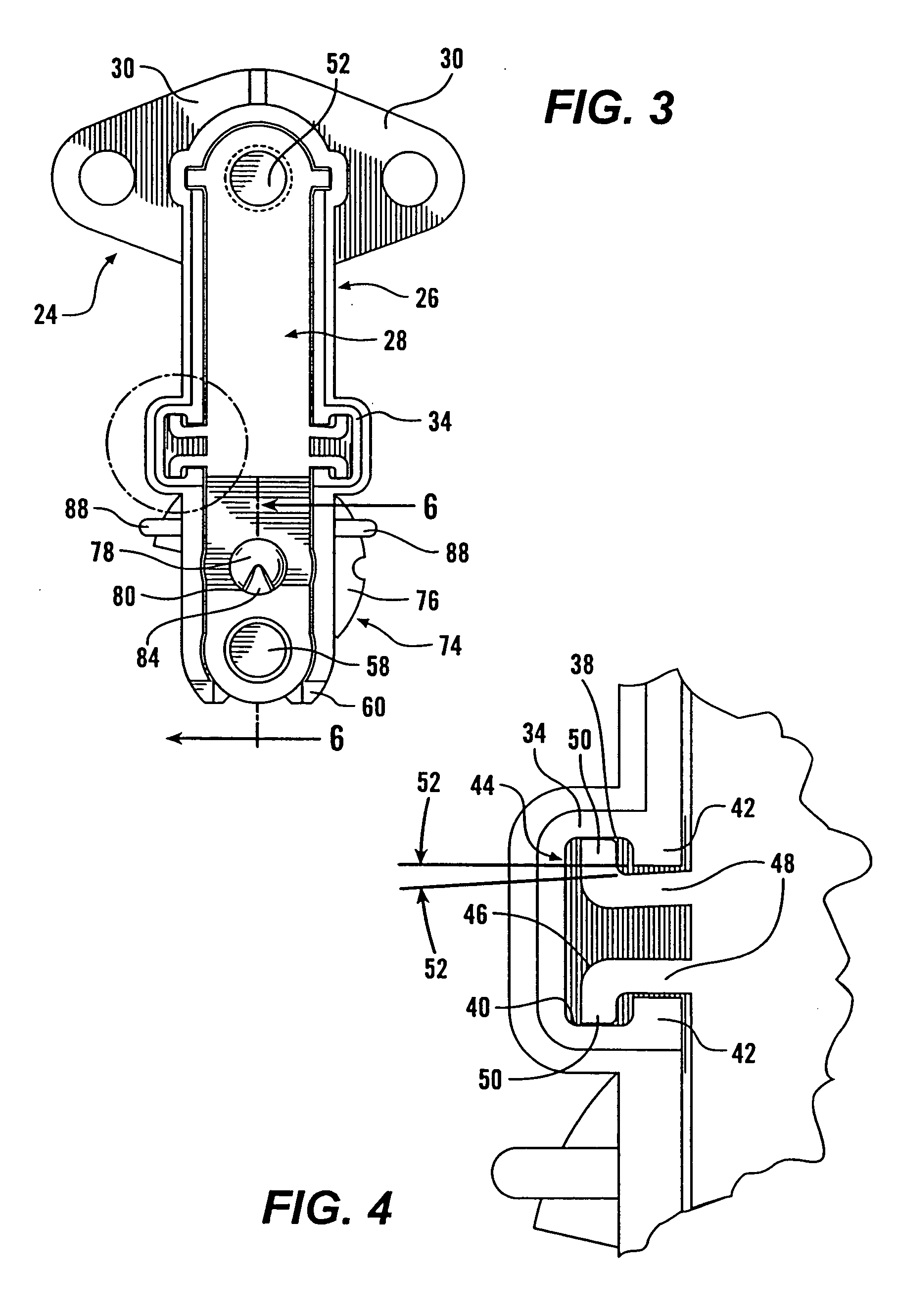
[0027] As shown in FIGS. 1 and 2, a sliding headlamp adjuster (identified generally as 24) in accordance with one embodiment of the present invention includes a base housing 26 with a slide 28 disposed at least partially therein. The base housing 28 has one or more mounting tabs 30 such that the adjuster 24 can be mounted to the back of a headlamp assembly support frame 32 (see FIG. 11). The amount and configuration of the tabs 30 can be configured as necessary for particular installations. Alternatively, a quarter-turn mounting system could be used. The base housing 26 has interior channels 34 running along its sides 36. When viewed from the exterior, e.g., FIG. 1, the channels 34 appear rectangular in cross-section. However, as shown in FIG. 3 and in detail in FIG. 4, on the interior, the channels 34 have a generally sideways T-shaped open cross section with a top T portion 38, a bottom T portion 40 and a narrower neck T portion 42.

[0028] As shown in FIGS. 3 and 4, the slide 28 h...


PUM


Abstract

A sliding adjuster includes a base housing with a slide positioned at least partially therein. The base housing includes mounting tabs so that the adjuster can be secured to the back of a headlamp assembly support frame. The base housing includes channels along its sides in which rails extending from the slide are disposed. A ball stud extends from the slide, the ball of which is engaged in a reflector within the headlamp assembly such that axial movement of the ball stud causes movement of the reflector. Movement of the slide is caused by rotation of an adjustment screw that is threaded into the slide but held in axial position with respect to the base housing. The adjuster may include a vehicle headlamp aiming device (“VHAD”) if required for the particular application.

Description

PRIORITY CLAIM / CROSS REFERENCE [0001] This is a continuation application of U.S. patent application No. 10 / 224,612 filed Aug. 20, 2002, which is a continuation of U.S. patent application Ser. No. 09 / 504,250, now U.S. Pat. No. 6,474,850 issued Nov. 5, 2002, which are hereby incorporated in their entireties for all purposes.FIELD OF THE INVENTION [0002] This invention relates generally to adjuster mechanisms, and more particularly to a sliding headlamp adjuster mechanism for use in motor vehicles. BACKGROUND OF THE INVENTION [0003] In traditional sealed beam style headlamps, the lamp's aim is adjusted by rotating one or more screws that hold the frame of the lamp to the vehicle. Such adjustment is made from the front of the vehicle by inserting a screwdriver or the like between the lamp frame and the vehicle trim and turning the screws to alter the orientation of the lamp and effectuate the desired adjustment. As the design of motor vehicles has evolved, headlamps have continually bee...

Claims


Application Information

Patent Timeline
IPC IPC(8): B60Q1/068
CPCY10T74/18656B60Q1/0683
Inventor BURTON, JOHN E.
Owner BURTON TECH
Why Eureka
Try Eureka